VVerdoos
Log in
CY

cykeo6688

@cykeo6688

71 Posts0 Followers0 Following
CY
cykeo6688@cykeo6688· Thursday at 7:42 AM

RFID Tool Cabinet for Tool Risk Management

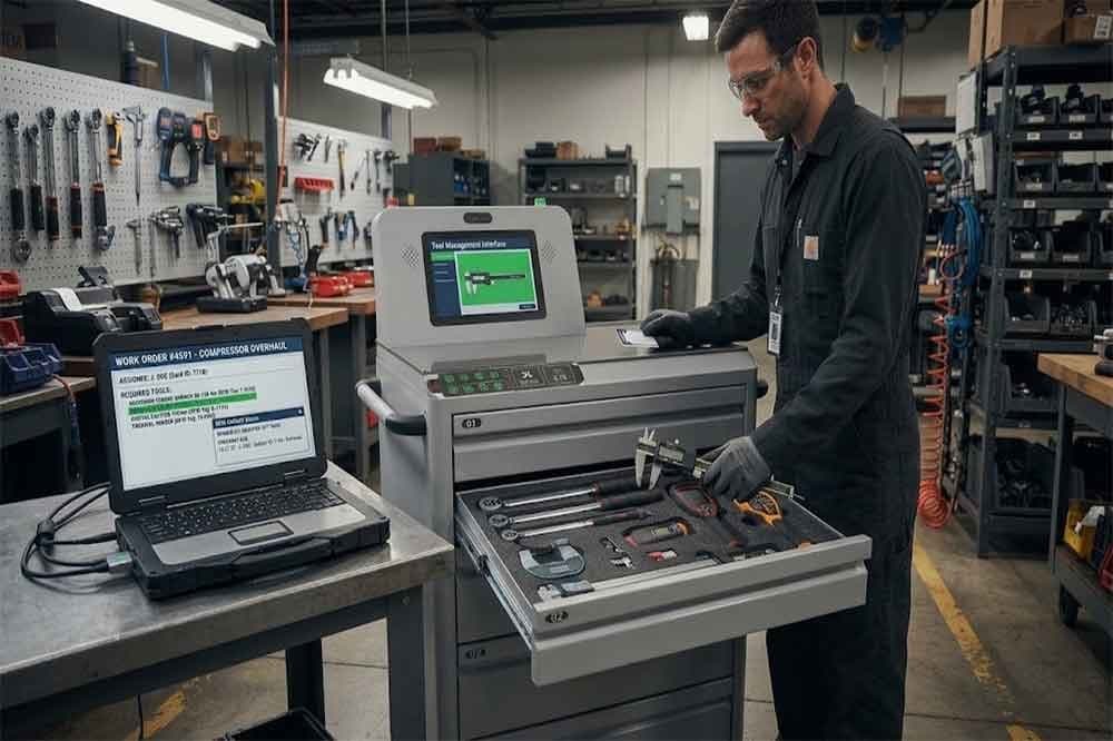
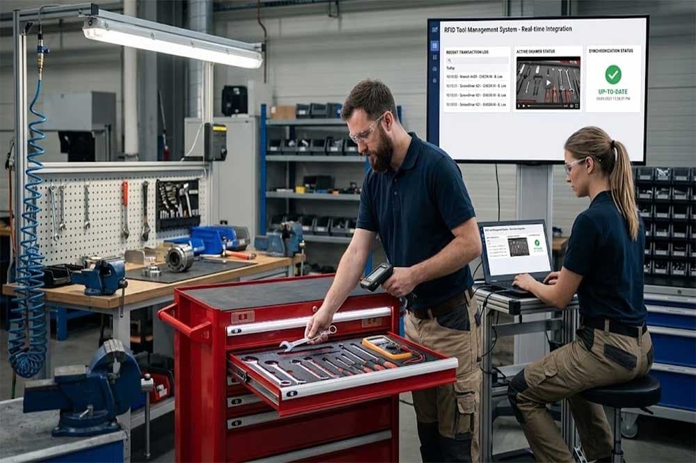
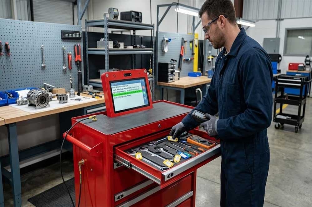
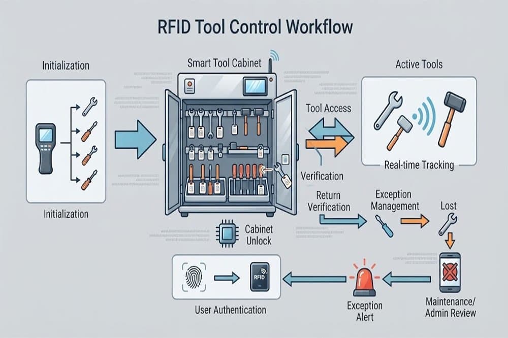
RFID Tool Cabinet for Tool Risk Management: Identify Problems Before They Escalate A missing screwdriver and an unavailable torque wrench may both appear as tool management problems, but the consequences can be very different. One may cause a short delay in a routine maintenance task. The other could interrupt a production line, delay a quality inspection, or leave a critical job waiting for equipment. Industrial companies do not need the same level of control for every tool. They need to understand which tools create the greatest operational, financial, quality, or safety risks and decide how those risks should be managed. An RFID tool cabinet can support this work by improving tool identification, recording checkout and return events, supporting configured access rules, and making selected tool statuses easier to review. When these functions are connected to a clear risk management process, teams can respond more consistently to missing tools, overdue returns, restricted equipment, and recurring shortages. The cabinet is not a complete risk management system by itself. Its value depends on how the company classifies tools, defines control requirements, handles exceptions, and uses the information collected. What Is Tool Risk Management? Tool risk management is the process of identifying problems that could arise from storing, issuing, using, maintaining, or losing industrial tools, then applying controls appropriate to their potential consequences. The risks vary by workplace. A general-purpose wrench may mainly create a replacement cost if it goes missing. A calibrated measuring instrument may introduce quality concerns if its status is uncertain. A specialized maintenance tool may cause production delays if it cannot be located when needed. A practical risk management process usually includes identifying tools and possible failure scenarios, estimating their likelihood and impact, selecting controls, assigning responsibility, and reviewing whether those controls are working. An RFID tool cabinet can contribute to several parts of this process. It can help establish which tools are registered, record supported transactions, associate events with users, and provide information about recorded availability or status. These records can help teams investigate risk events and identify patterns. For example, repeated overdue returns from one department may indicate a workflow problem, while frequent requests for an unavailable tool may reveal a shortage or allocation issue. The important point is that risk management starts with understanding the consequences of a problem. RFID provides useful information and control options, but people still need to assess the risks and decide what action is appropriate. Industrial tools classified by operational criticality, access requirements, and potential impact. Which Tool Risks Should Companies Consider? Tool loss and unexplained inventory differences Tools may disappear gradually rather than in one obvious incident. An item is borrowed without a complete transaction, returned to the wrong storage area, or moved to another department without updating its record. Over time, the digital register and physical inventory no longer match. An RFID-enabled cabinet can support inventory verification and record tool checkout and return events. When a discrepancy appears, supervisors can review the available transaction history and investigate whether the issue involves an incomplete return, an incorrect record, or a genuinely missing item. This does not guarantee that every loss will be prevented. The effectiveness depends on tag readability, cabinet design, transaction rules, and whether tools are required to pass through the controlled workflow. Production delays caused by unavailable tools Some tools are inexpensive but operationally critical. A particular fixture, service tool, or specialized instrument may be required for one specific maintenance procedure. If that item is missing, being repaired, or already allocated to another team, the cost of the delay may exceed the replacement value of the tool. An RFID tool cabinet can help teams review recorded availability, outstanding checkouts, and recurring demand. Combined with work-order planning, these records can reveal which tools deserve closer availability monitoring or a backup plan. For more detailed guidance, companies can also review RFID tool downtime management and RFID tool demand planning. Unauthorized access or use Some tools are expensive, sensitive, specialized, or subject to internal restrictions. Uncontrolled access can increase the risk of loss, misuse, or use by personnel who have not received the required training. A compatible RFID cabinet system may support user authentication, permissions, and transaction records. These features can help a company apply different access rules to different tool categories. However, a recorded user identity does not prove that the tool was used correctly after checkout. Where misuse could have serious consequences, additional safeguards, supervision, training, and work procedures may be necessary. Tools used in unsuitable condition A tool can be physically available but not ready for use. It may be damaged, awaiting repair, overdue for inspection, or subject to a restriction that has not been reflected in the cabinet’s current status. This creates a different kind of risk from ordinary tool loss. The concern is not simply whether the tool can be found, but whether it should be issued. A tool management platform can link tools to maintenance or inspection information when the relevant data is available. Depending on the system, it may display warnings, flag restricted items, or enforce configured checkout rules. The company must define the status categories and ensure that inspection or maintenance information remains accurate. Poor visibility across departments A tool may be available somewhere in a factory but remain unavailable to the team that needs it. Different departments may maintain separate registers, use different naming conventions, or follow inconsistent transfer procedures. This makes it difficult to understand the overall exposure created by shared equipment. A coordinated RFID tool management system can help standardize tool identities and record movements between cabinets or locations where the required functionality is supported. This gives managers a better basis for reviewing shared resources and deciding where stronger controls are needed. Classify Tools According to Risk One of the most useful steps is to stop treating all tools as equally important. A simple classification process can group tools according to factors such as replacement value, operational criticality, inspection requirements, access restrictions, loss history, and the consequences of incorrect use. Technician authenticating at an RFID tool cabinet with different access permissions for controlled industrial tools. For example, a factory might use three broad categories: Risk category Typical characteristics Possible controls Standard Common tools with limited operational impact Basic identification, checkout records, periodic inventory Controlled Higher replacement cost, frequent demand, or restricted access User permissions, closer transaction review, exception alerts Critical Significant production, quality, or safety consequences if unavailable or misused Defined authorization, status checks, escalation procedures, contingency planning These categories are illustrative rather than universal. A company should adapt them to its own equipment, processes, and risk assessment. A low-cost tool may still deserve critical status if a production process cannot continue without it. Conversely, an expensive tool may not require the strictest operational controls if the consequences of loss or misuse are limited. Risk classification should therefore reflect both the probability of a problem and the potential impact. Use a practical risk scoring method A simple risk score can help teams prioritize their attention. One common approach is to score likelihood and impact separately, then multiply the two values. For example: Risk score = Likelihood score × Impact score If each factor is scored from one to five, the resulting score ranges from one to twenty-five. A tool with a likelihood score of four and an impact score of five receives a score of twenty. A tool with a likelihood score of two and an impact score of two receives a score of four. The numbers are only a prioritization aid. They do not provide a precise prediction of future events, and different risks may require separate treatment even when their scores are similar. Teams should document their scoring criteria and review them when operating conditions change. A frequently missing tool may deserve a higher likelihood rating, while a tool used in a newly critical process may need a higher impact rating. How an RFID Tool Cabinet Supports Risk Controls Improve tool identification and recorded status Risk decisions are difficult when the company cannot reliably identify the affected tool. Each managed tool should have a unique asset record linked to its RFID tag. The record may contain the tool category, location, responsible department, current status, and relevant risk classification. This allows the management platform to distinguish between tools that look similar but have different control requirements. For example, two visually identical measuring instruments may have different inspection dates or restrictions. Their records should not be combined simply because the models match. Accurate identification creates a foundation for more targeted control rules and more reliable investigations. Record transactions that matter Checkout and return events can provide useful evidence about how tools move through the workplace. Depending on the system configuration, a transaction may record the tool ID, user ID, timestamp, cabinet, and event type. Transfer or exception events may also be recorded if the software supports them. These records can help managers investigate overdue tools and identify recurring patterns. If one category regularly remains checked out beyond the expected period, the team can review whether return rules, work scheduling, or storage arrangements need to change. The goal is not to collect every possible data point. It is to capture enough reliable information to support the decisions that matter. Apply risk-based access rules Risk classification can guide cabinet permissions. Standard tools may be available through a routine checkout process, while selected equipment may require a specific user role, supervisor approval, or another configured authorization step. The rules should be clear enough for employees to follow without creating unnecessary delays. Emergency access also needs attention: if a critical maintenance job cannot wait, the company should define how an authorized exception is approved and recorded. Review permissions when employees change roles, temporary assignments end, or departments reorganize. Otherwise, outdated permissions can create avoidable exposure. For more detail, see RFID tool cabinet access control. Support exception alerts and escalation An exception becomes more useful when someone knows what action to take. Examples include a critical tool remaining checked out beyond its expected return time, an inventory discrepancy involving a high-risk item, or an item whose status indicates that it should not be issued. Where supported, an RFID tool management platform can generate alerts or reports for these events. The company should then define who receives the alert, how quickly it should be reviewed, and when the issue must be escalated. Not every exception requires the same response. A short delay involving a common hand tool may need a reminder. An unexplained discrepancy involving critical equipment may require an immediate inventory check and supervisor review. The response should reflect the actual risk rather than relying on a single rule for every event. Make recurring risk patterns easier to identify A single missing tool may be an isolated incident. Repeated missing tools from the same work area could indicate a deeper problem. Transaction histories and exception reports can help identify recurring issues, such as frequent overdue returns, repeated status overrides, tools often unavailable during planned maintenance, or unusually high demand for specific equipment. Managers can use these patterns to adjust storage locations, clarify responsibilities, revise checkout periods, purchase backup tools, or improve employee training. For related operational metrics, see RFID tool cabinet reporting and analytics. Build a Risk Register for Managed Tools A risk register helps turn observations into assigned actions. It does not need to be complicated, particularly during a pilot project. A useful register might include the following fields: Field Purpose Tool ID and category Identifies the equipment under review Risk scenario Describes what could go wrong Likelihood and impact Establishes a consistent priority Existing controls Records what is already in place Additional action Defines the proposed risk response Responsible person Assigns ownership Review date Sets a point for reassessment Current status Shows whether the action is open or complete For example, a specialized maintenance tool may have a high impact rating because its absence can delay a critical repair. Existing controls might include a cabinet checkout record, while an additional action could be to introduce a return-time review and identify a backup source. The risk register should remain connected to the real operating process. If it becomes a spreadsheet that nobody updates, it will provide little ongoing value. An RFID tool cabinet can supply some of the operational information used during reviews, but risk ratings, action ownership, and decisions may need to remain in a separate maintenance, quality, or risk management system. Connect Tool Risk Information With Maintenance and Planning Tool risk does not exist in isolation. Maintenance teams may know that a particular tool is essential for a planned repair. Quality teams may know that a measuring instrument must have a current calibration status. Production planners may know that several work orders require the same limited equipment. Combining these perspectives can improve decisions about tool availability and control. Where system interfaces support it, an RFID tool management platform may exchange tool identities and transaction information with a computerized maintenance management system, enterprise resource planning platform, or other operational software. For example, a maintenance planner could review whether required tools are recorded as available before scheduling a job. A tool manager could use demand history to identify frequently contested equipment. A quality team could review the recorded status of controlled instruments before use. The implementation should define which system owns each authoritative record and how updates are synchronized. If a connected system becomes unavailable, staff need a documented process for handling transactions and reconciling records afterward. Integration should be tested with actual workflows rather than judged only by the presence of an API or a software connection. RFID tool cabinet platform connected with maintenance, quality, and planning systems for tool status visibility. How to Implement Risk-Based RFID Tool Management Start with the most consequential risks Do not begin by trying to apply advanced controls to every item in the factory. Choose a tool group where a problem would have a meaningful impact, such as critical maintenance equipment, high-value tools, or instruments with specific inspection requirements. Document the main risk scenarios and the controls already in place. This provides a baseline for deciding what the RFID cabinet should help improve. Confirm the required system functions Translate the risk scenarios into specific requirements. A project may need unique tool identification, user authentication, transaction history, configurable permissions, status warnings, exception reporting, or integration with maintenance records. Ask the supplier to demonstrate each important function. If a requirement is to prevent checkout of restricted tools, confirm whether the proposed system can enforce the rule or only display a warning. Test normal operations and failure scenarios A pilot should include everyday checkout and return tasks, but that is only the beginning. Test missing tags, duplicate-looking tools, overdue returns, restricted status, unauthorized access attempts, damaged returns, and network interruptions. Check how the system records each event and whether employees can follow the required response. For critical equipment, test the escalation process as well. An alert is useful only if the responsible person receives it and knows what to do. Define measurable indicators Choose a small set of indicators that reflect the original risk. Possible measures include overdue returns for critical tools, inventory discrepancies, time needed to locate a required item, repeated access exceptions, or tool-related delays in maintenance work. Compare results with a reliable baseline and allow for differences in workload or production conditions. Do not assume that every improvement is caused by the cabinet alone. Review and adjust the controls After the pilot, review whether the controls are reducing the intended exposure without creating excessive work. A rule that is too strict may encourage employees to bypass the process. A rule that is too loose may fail to address the original risk. Use feedback from operators, supervisors, maintenance staff, and IT personnel to refine the workflow before expanding to more tool categories or locations. Common Mistakes in Tool Risk Management One common mistake is classifying risk only by purchase price. A low-cost tool may be essential to production, while a more expensive item may have limited operational impact. Classification should consider consequences, likelihood, and use conditions. Another mistake is assuming that RFID automatically prevents tool loss. The system can improve identification and recordkeeping, but results depend on tag performance, cabinet design, transaction compliance, and the procedures used outside the cabinet. Companies may also create too many alerts. If every minor delay triggers the same urgent notification, staff can begin to ignore them. Prioritize events according to their impact and assign clear response responsibilities. A further problem is failing to maintain tool status information. An RFID record cannot provide a reliable risk signal if the underlying inspection, maintenance, or location data is outdated. Finally, some projects measure only how many tools have been tagged. Tagging is an implementation milestone, not proof that operational risk has been reduced. The more useful question is whether the controls help prevent, detect, or resolve the specific problems identified at the start. Choosing an RFID Tool Cabinet for Risk Management When evaluating an RFID tool cabinet, begin with the risks the system is expected to address. Review tool identification accuracy, cabinet access options, user authentication, transaction records, status management, exception handling, reporting, and supported software interfaces. The required features will depend on the tool categories and the operating environment. Ask practical questions during evaluation: Can the system distinguish individual tools with similar models or appearances? Which checkout, return, and access events are recorded? Can different permissions be configured for different tool categories? Can restricted status be enforced, or is it only displayed? How are overdue returns and unresolved discrepancies handled? Can records be exported or shared with existing maintenance software? What happens during network or synchronization failures? Can the system support the company’s expected number of users, tools, and locations? For a broader purchasing review, use an RFID tool cabinet procurement checklist. A structured RFID tool cabinet pilot project can then verify whether the selected functions address the real risks before full deployment. The best solution is not necessarily the one with the longest feature list. It is the one that provides dependable information and workable controls for the risks the organization actually faces. Conclusion RFID tool cabinets can support industrial tool risk management by improving identification, recording tool movements, supporting configured permissions, and making selected exceptions easier to investigate. When this information is used alongside a risk register, maintenance planning, and clear operating procedures, teams can make more informed decisions about which tools need stronger controls. The process should begin with risk, not hardware. Identify the tools whose loss, unavailability, restricted status, or misuse could have the greatest consequences. Define suitable controls, test them with actual workflows, and measure whether they improve the intended outcomes. RFID does not eliminate every risk, and it cannot replace sound maintenance, safety, or quality practices. Used as part of a well-designed process, however, it can help organizations move from reacting to missing or unavailable tools toward more consistent, evidence-based risk control. https://www.cykeorfid.com/rfid-product/rfid-smart-cabinet/rfid-tool-cabinet/
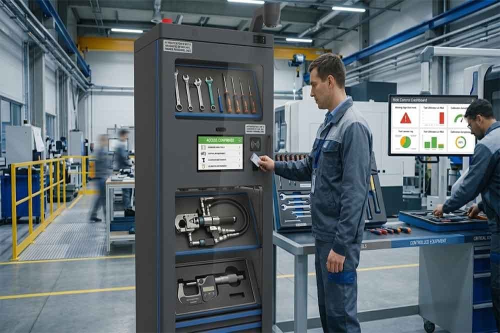
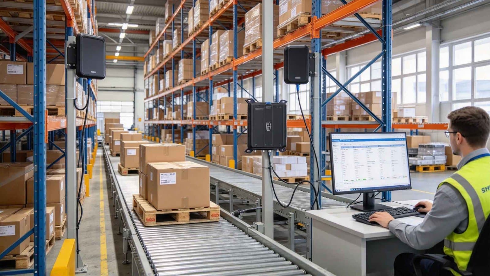
Photo shared by cykeo6688: RFID Tool Cabinet for Tool Risk Management: Identify Problems Before They Escalate
A missing screwd
CY
cykeo6688@cykeo6688· Wednesday at 7:08 AM

what is an rfid device

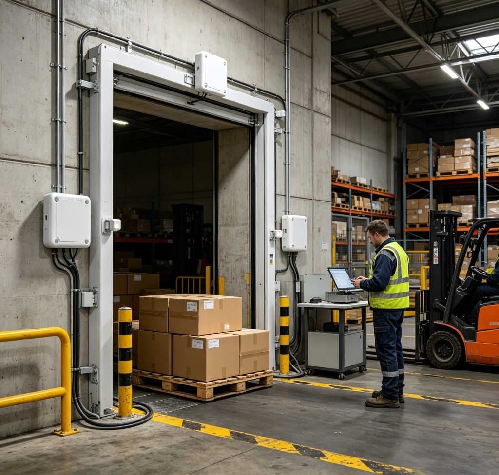
What is an rfid device? An RFID device is electronic hardware that uses radio-frequency communication to identify, read, and sometimes write RFID tags. In UHF RFID systems, the device normally works with passive tags, antennas, and software to capture item-level identification data without requiring direct line of sight. For business applications, the phrase RFID device usually refers to equipment such as a UHF RFID reader, handheld reader, fixed reader, desktop reader, or RFID reader module. The exact hardware depends on where the identification task takes place. GS1 identifies passive UHF RFID as RAIN RFID and states that these systems use the 860–930 MHz range and comply with GS1/EPC Gen2 and ISO/IEC 18000-63. GS1 also identifies fast asset identification, inventory, and tracking as major UHF RFID applications. What Is a UHF RFID Device Used For? A UHF RFID device is mainly used to identify tagged objects quickly within a defined RF reading area. Typical applications include: Warehouse inventory Asset identification Logistics and shipment handling Retail item tracking Apparel management Tool management Library inventory Textile and laundry management Production-line identification Tag registration and rewriting The useful difference becomes obvious on the shop floor. A worker can move past a shelf of tagged items with a handheld UHF reader and collect several tag IDs without stopping to align a scanner with each individual label. GS1 notes that RAIN RFID does not require the same line-of-sight interaction as barcode scanning and can support rapid inventory collection. UHF RFID Device Components UHF RFID Reader The reader is the active electronic component that communicates with the RFID tag. Depending on the application, it may be: Device type Typical application Fixed UHF RFID reader Warehouse portals, conveyors, production lines Handheld UHF reader Shelf inventory, asset searching, field operations Desktop RFID reader Tag registration and controlled read/write OEM RFID module Embedded RFID equipment and customized systems The reader does not operate alone. In a conventional UHF installation, the reader, antenna, RFID tag, communication interface, and application software form one working system. UHF RFID Tag The passive UHF RFID tag contains an RFID chip and RFID antenna. The tag responds when it receives sufficient RF energy from the reader. The data structure can include an EPC and, depending on the tag and application, additional user memory. GS1 states that a typical RAIN RFID tag carries no more than about 8 KB of data, while simple license-plate style tags may use a 96-bit or 128-bit identifier. That distinction matters when specifying tags. Many inventory applications do not need large amounts of information stored directly on the tag. A unique identifier can be enough for the software to retrieve the detailed product record. How Does a UHF RFID Device Work? The operating sequence is straightforward: The UHF RFID reader generates an RF field. A compatible passive tag enters the reading area. The tag responds through backscatter communication. The reader receives the tag response. The reader processes the identification data. Software uses the data as an inventory, tracking, or identification event. GS1’s RAIN RFID architecture describes the reader as the equipment used to read and write tagged items, manage the resulting data, and trigger actions within a solution. The important point is that the RFID device does not magically “track” an object by itself. It creates an identification event. The application determines what that event means—received goods, an inventory count, a tool return, or another business transaction. Why UHF RFID Is Used for Fast Identification UHF RFID is particularly useful when many tagged objects must be identified within a short period. GS1 describes RAIN RFID as being designed for fast asset identification, inventory, and tracking, with read ranges that can reach up to 10 meters depending on the environment. That number should not be treated as a guaranteed operating distance. In an actual warehouse, tag orientation, antenna position, reader power, packaging, metal structures, liquids, RF interference, and tag density can change the result. In field testing, the shape of the reading zone is often more important than the maximum range printed on a specification sheet. A well-controlled 3-meter reading zone can be more useful than an uncontrolled 10-meter zone if the application needs to identify only the cartons passing through a doorway. UHF RFID device reading tagged cartons in a European warehouse A fixed UHF RFID device identifies tagged cartons as they pass through a controlled warehouse reading zone. UHF RFID Device and RFID Standards UHF RFID equipment used for supply-chain applications commonly follows the GS1/EPC Gen2 ecosystem. GS1’s current EPC Gen2 standard identifies the UHF RFID air-interface technology as operating in the 860–960 MHz range, while regional implementations determine the actual permitted frequency and power conditions. GS1’s current standard page records Release 3.0.1 as ratified in February 2026. For equipment buyers, standards compatibility is therefore more useful than simply comparing a reader’s advertised read distance. A UHF RFID device should be evaluated according to: Supported RFID protocol Regional frequency requirements Reader output power Antenna configuration Tag compatibility Multi-tag performance Communication interface Software and SDK support Required reading-zone size For Cykeo applications, this is particularly relevant when a UHF RFID device is being integrated into an existing inventory, logistics, tool, textile, or asset-management workflow. What Is an RFID Device Used for in Real Applications? A UHF RFID device becomes useful when physical items need to be identified repeatedly without stopping the workflow. In a warehouse, for example, the reader can be installed beside a receiving or shipping passage. Tagged cartons pass through the defined RF zone, and the system records the tag IDs detected at that point. The same principle works on a smaller scale. A technician can carry a handheld UHF RFID reader along a tool shelf. A retailer can use a reader to count tagged apparel. A textile facility can identify reusable linen as it moves between processing stages. The hardware changes. The underlying task does not: turn a physical tagged object into machine-readable identification data. UHF RFID Device Types and Their Working Environments Fixed UHF RFID Devices Fixed readers are permanently installed at a defined location. Typical deployments include: Warehouse entrances and exits Conveyor systems Production lines Sorting stations Asset checkpoints Retail back rooms A fixed installation gives the engineer more control over antenna direction, reader position, cable routing, and reading-zone boundaries. This is where installation experience matters. Moving an antenna only a small distance can change the shape of the RF field around a doorway or conveyor. Handheld UHF RFID Devices Handheld devices put the reader in the operator’s hands. They are useful when the reading location changes frequently: Shelf inventory Warehouse cycle counting Asset searching Tool inspection Retail stock checking Field maintenance A handheld reader also changes the operator’s workflow. Instead of bringing every item to a scanner, the operator brings the reader to the items. Desktop UHF RFID Devices Desktop readers are designed for controlled workstations. They are particularly useful for: RFID tag registration Tag encoding Tag rewriting Library registration Tool entry Textile registration Here, long reading distance is not necessarily desirable. If an operator is writing one tag, detecting another tag several metres away could create a data-management problem. A defined near-field working area gives the operator much tighter control. UHF RFID Device Performance: What Should Be Measured? Read Rate Is More Useful Than Maximum Distance A specification such as “10-meter read range” tells only part of the story. During a real deployment, I would pay closer attention to whether the reader consistently identifies the intended tags under actual operating conditions. Useful measurements include: Performance factor What to observe Read rate How consistently tags are identified Read zone Where tags can actually be detected Multi-tag performance Behavior when many tags respond together Write performance Whether compatible tags are written reliably RSSI Relative received signal strength Filtering Ability to exclude unwanted tag data Stability Performance during continuous operation This is particularly important with UHF RFID because the RF environment is rarely perfectly clean. Metal shelving, liquid products, dense cartons, cable trays, machinery, and tag orientation can all affect the result. The reader should therefore be tested with the actual tag and actual product, not only with a loose sample tag on an open workbench. Why Anti-Collision Matters in a UHF RFID Device Multi-Tag Reading in Dense Environments UHF RFID is often selected because many tags can be identified without individually presenting each item to the reader. That creates another engineering requirement: the reader must manage multiple tag responses. An RFID reader uses anti-collision procedures to communicate with tags without treating simultaneous responses as one unreadable signal. This becomes particularly noticeable in: Packed cartons Clothing racks Warehouse shelves Tool cabinets Library collections Textile bundles Cykeo’s UHF RFID platforms use anti-collision and filtering functions to support dense tag recognition. In practical testing, I would not judge the system only by the number of tags detected during one short scan. Repeating the test while changing tag orientation, spacing, product arrangement, and operator movement usually reveals much more. UHF RFID Device Output Power and Reading Zones Reader output power affects the RF field, but maximum power is not automatically the correct setting. A higher output can enlarge the operating area. It can also increase the possibility of detecting tags that are outside the intended process. For a warehouse portal, a broader reading zone may be useful. For a tag-writing workstation, it may be undesirable. Cykeo’s RFID reader products can provide adjustable RF output according to the product configuration. For example, the CYKEO-M4L OEM RFID module supports output adjustment up to 33 dBm, with 1 dBm adjustment steps. That kind of control is valuable during commissioning because engineers can tune the system around the physical reading requirement rather than simply operating at maximum output. How RFID Device Software Fits Into the System Reader Data Is Only the Beginning An RFID reader produces identification data. The application decides what happens next. A typical UHF RFID system may look like: RFID tag → antenna → reader → communication interface → application → database The application might turn a tag ID into: Product information Asset information Inventory quantity Receiving event Shipping event Tool-borrowing record Textile circulation record For custom development, the communication method and software tools deserve attention before hardware is finalized. Cykeo’s RFID development ecosystem includes SDK/API resources for supported products, while its desktop RFID platform provides C# and Java development materials for integration. That matters when the reader needs to become part of an existing business application rather than operate as an isolated demonstration device. How to Select a UHF RFID Device Before choosing a reader, document the physical workflow. 1. Define the Reading Area Is the reader operating over: A desk? A shelf? A doorway? A conveyor? A production station? An open warehouse? The answer immediately narrows the hardware options. 2. Define Tag Density Reading one tag is fundamentally different from reading 50, 100, or several hundred tags in close proximity. 3. Test the Actual Product Do not test only an RFID inlay on a clean table. Test the finished carton, garment, tool, container, or textile. 4. Check Regional Requirements UHF RFID operating conditions vary by region. Frequency and permitted power must match the target market. 5. Check Communication and Integration USB, RS-232, Ethernet, APIs, SDKs, and software documentation can all influence how quickly the device becomes part of a working system. 6. Define Read and Write Requirements If tags only need to be identified, read-only operation may be sufficient. If tags must be initialized or rewritten, reader write capability, tag memory, permissions, and software support must be considered together. Desktop UHF RFID device registering tags at a professional European workstation A desktop UHF RFID device provides a controlled reading and writing area for RFID tag registration. Common UHF RFID Device Questions 1. What is an RFID device? An RFID device is hardware used to communicate with RFID tags and process their identification data. In UHF applications, it commonly refers to a fixed reader, handheld reader, desktop reader, or embedded RFID module. 2. What is a UHF RFID device used for? A UHF RFID device is used for fast identification of RFID-tagged objects. Common applications include inventory, logistics, asset management, retail, textile management, tool tracking, library systems, and production operations. 3. Can a UHF RFID device read multiple tags? Yes. UHF RFID readers are designed to identify multiple compatible tags within their operating zone. Anti-collision processing allows the reader to manage multiple tag responses. 4. How far can a UHF RFID device read? The distance varies according to reader power, antenna configuration, tag characteristics, orientation, materials, RF interference, and regional operating requirements. GS1 notes that RAIN RFID can reach up to 10 meters depending on the environment, but actual deployment distance must be tested. 5. Can a UHF RFID device write to tags? Some UHF RFID devices support both reading and writing. The reader, tag, memory configuration, protocol, permissions, and application software must all support the required operation. 6. Does UHF RFID require line of sight? No. UHF RFID does not require the direct optical line of sight used by barcode scanning. However, materials, tag orientation, metal, liquids, and the RF environment can strongly affect communication. 7. Is a UHF RFID reader the same as an RFID tag? No. The reader is the electronic device that communicates with the tag. The RFID tag is attached to the physical object and responds to the reader’s RF communication. They perform different roles within the RFID system. What Is an RFID Device? The Practical Answer An RFID device is the hardware layer that allows an RFID system to identify tagged objects through radio-frequency communication. For UHF RFID, that hardware can be a fixed reader, handheld reader, desktop reader, or embedded module. The correct choice depends on the physical process—not simply on the reader’s maximum range or output power. A warehouse may need a fixed reader and carefully positioned antennas. A technician counting shelf inventory may need a handheld device. A label administrator may need a desktop UHF RFID device with a tightly controlled read/write area. That distinction is where RFID projects move from a specification sheet to a working system. What is an RFID device? In practical UHF RFID applications, it is the hardware that connects physical tagged objects with usable digital identification data, allowing businesses to collect inventory, asset, logistics, registration, and tracking information more efficiently. https://www.cykeorfid.com/rfid-product/rfid-modules/

Photo shared by cykeo6688: What is an rfid device? An RFID device is electronic hardware that uses radio-frequency communicatio
CY
cykeo6688@cykeo6688· Tuesday at 8:11 AM

RFID Tool Cabinet for Tool Asset Management: Better Visibility and Control of Industrial Tools

Industrial tools are assets, even when they are too small to appear on a company’s main equipment register. Torque wrenches, measuring instruments, maintenance tools, power tools, and specialized production equipment can all carry a purchase cost and an operational responsibility. When these items move between departments, technicians, workshops, and storage locations, maintaining reliable records becomes difficult. An RFID tool cabinet can help connect physical tools with digital asset records. Instead of relying entirely on spreadsheets or manual sign-out sheets, a company can use RFID identification, cabinet transactions, and management software to improve visibility into tool identity, location, availability, and responsibility. The objective is not simply to count tools. It is to make tool assets easier to identify, manage, audit, and allocate throughout daily operations. What Is RFID Tool Asset Management? RFID tool asset management is the process of identifying, recording, locating, and controlling tools with the help of radio frequency identification technology and connected management software. Each managed tool is associated with a digital record. Depending on the application, this record may contain a tool ID, description, category, department, assigned location, purchase information, responsible user, condition, and maintenance references. An RFID tag provides a way to identify the physical tool. An RFID reader or cabinet reading system detects compatible tags, while software associates the captured identification data with the corresponding asset records. An RFID smart tool cabinet adds a practical control point to this process. It can support tool storage, user authentication, checkout and return recording, and inventory checks. The exact functions depend on the cabinet hardware, software configuration, and integration requirements. For factories managing hundreds or thousands of tools, this connection between physical storage and digital records can make routine asset management more consistent. Why Industrial Tool Assets Are Difficult to Manage Many factories already have an asset register. The problem is that the register does not always reflect what happens on the workshop floor. A spreadsheet may show that a tool belongs to the maintenance department, but the tool could be in a technician’s toolbox, on a production line, awaiting inspection, or temporarily stored in another workshop. These gaps create several practical problems. RFID-tagged industrial tools linked to unique asset IDs and digital management records. Asset records become outdated Tools may be transferred between departments without updating their assigned locations. Staff may also replace a damaged tool, change its storage position, or lend it to another team without updating the relevant records. Over time, the asset register and physical inventory can become inconsistent. Responsibility is difficult to establish When several technicians share the same equipment, it may be unclear who last checked out a tool or who should return it. This is especially challenging for expensive, specialized, or frequently shared tools. Manual audits consume time A conventional asset audit may require employees to visit storage locations, read labels, compare serial numbers, and update spreadsheets. If tools are distributed across multiple locations, the work becomes more complicated. Asset availability is not always clear A tool may exist in the asset register but still be unavailable for work. It could be checked out, misplaced, damaged, reserved, or awaiting inspection. For maintenance and production teams, knowing that a tool exists is not enough. They also need to understand its current operational status. How RFID Tool Cabinet Supports Asset Management Connect each tool with digital asset record The first step is to establish a reliable identity for every managed tool. A tool can receive a unique asset ID and a suitable RFID tag. The corresponding software record stores the tool’s basic information and links the physical item to its digital identity. The record might include the tool category, model, serial number, department, storage location, and asset status. Additional fields can be included when needed. RFID tags do not necessarily need to store all this information themselves. In many deployments, the tag provides an identifier, while the main record remains in the management system. This arrangement makes it easier to update asset information without rewriting the entire record on the physical tag. Improve visibility into tool locations An RFID tool cabinet provides a defined location where tools can be stored and identified. When a tool is checked out or returned through a supported workflow, the system can record the transaction and update the associated location or custody information. Where several cabinets are connected to a shared platform, authorized users may be able to view tool records across departments or facilities. However, a cabinet transaction does not automatically prove the exact real-time location of a tool after it leaves the cabinet. If a technician carries the tool to another work area, the system needs an additional recording method or tracking infrastructure to establish its subsequent location. Clear rules for transfers, returns, and temporary storage help keep location records useful. Record tool custody and responsibility Asset management often requires more than knowing where a tool is stored. Managers also need to know who has taken responsibility for it. A connected cabinet can support user authentication and tool checkout records. Depending on the configuration, a transaction may link a tool, user, timestamp, and cabinet location. These records help supervisors investigate missing tools, review borrowing history, and identify repeated problems in a shared tool room. For high-value assets, permission rules can also restrict access to selected tools or categories. The system should match these rules to actual job responsibilities rather than making access unnecessarily complicated. Make asset inventory easier to maintain RFID identification can reduce the amount of manual work required for routine tool checks. A compatible cabinet may identify multiple tagged tools during an inventory process, depending on the tag design, tool materials, cabinet structure, antenna arrangement, and reading configuration. The resulting records can be compared with the expected inventory to identify discrepancies. Staff can then investigate missing, unexpected, or incorrectly registered tools. RFID does not guarantee perfect reading in every environment. Metal surfaces, closely packed tools, tag orientation, and overlapping read zones can affect performance. Representative tools should be tested before a system is deployed at scale. Connect asset status with daily operations A tool’s asset record becomes more useful when it reflects operational conditions. For example, a tool may be registered and present in a cabinet but unavailable because it is damaged or overdue for inspection. Another tool may be available but assigned to a different department. A well-designed system can distinguish between statuses such as available, checked out, under maintenance, awaiting inspection, and retired. The exact status model should reflect the company’s operating procedures. Where calibration or maintenance records are important, the asset management system can link to the relevant maintenance or quality software instead of keeping disconnected copies of the same information. What Information Should Tool Asset Record Contain? The required data depends on tool value, risk, usage, and company procedures. A practical starting point is to define a consistent record structure. Asset information Management purpose Unique asset ID Distinguishes one tool from another RFID tag ID Connects the physical tag with the digital record Tool name and category Makes search and reporting easier Model or serial number Supports identification and verification Assigned department Shows organizational responsibility Current recorded location Helps users find the tool Asset status Shows availability or restrictions Current custodian Supports accountability for checked-out tools Transaction history Records issue, return, and transfer events Maintenance or inspection reference Connects the tool with relevant service records Purchase or asset value Supports financial and replacement reviews where required Not every tool needs every field. Adding too many mandatory fields can make registration slow and increase the chance of incomplete records. A better approach is to define the minimum information needed for all tools, then add specialized fields for high-value equipment, calibrated instruments, or tools subject to stricter controls. RFID Tool Cabinets and Enterprise Asset Management Software RFID tool cabinet records connected with ERP and maintenance management software. An RFID cabinet can manage a defined tool storage and transaction workflow, but larger organizations may already use ERP, CMMS, MES, warehouse software, or an enterprise asset management platform. Integration can connect cabinet activity with these existing records. For example, ERP software may hold purchasing and financial information. A CMMS may manage maintenance activities and work orders. MES software may coordinate production operations. The RFID tool management layer can supply tool identification and transaction events where the interface supports them. Before integration, the project team should define which system owns each data field. If two systems can independently update a tool’s department or status, conflicting records may appear. The technical design should also specify how events are transmitted, how failed synchronization is handled, and how duplicate transactions are prevented. APIs, scheduled data exchange, or other supported interfaces may be appropriate depending on the existing software. A small pilot involving representative tools and actual users is often a practical way to validate these decisions before connecting multiple cabinets. How to Implement RFID Tool Asset Management Start with an asset audit Review the existing tool register and compare it with the tools physically available. Identify duplicate records, missing asset IDs, outdated locations, and inconsistent tool names. There is little value in automating a database that already contains major identification problems. Classify tools by management requirements Not every item needs the same level of control. Frequently shared tools, high-value equipment, precision instruments, and general-purpose hand tools may require different tag types, permissions, and record fields. Classification helps control implementation costs and keeps the workflow appropriate for each tool category. Test tags and cabinet reading performance Select representative tools, including metal tools and items with unusual shapes or dense storage arrangements. Test whether the proposed tags can be read reliably in the intended cabinet. Confirm how the system handles multiple tools, unexpected reads, and tools placed close together. Actual test results are more useful than relying on a reader’s maximum advertised range. Define location, custody, and status rules Decide what happens when a tool is issued, returned, transferred, sent for repair, or retired. For example, a checkout transaction might update custody without changing the tool’s home department. A transfer transaction might change the assigned location. Keeping these meanings separate helps avoid misleading records. Validate reports and integration Before full deployment, compare cabinet records with physical checks. Confirm that users can locate tools, supervisors can review transaction histories, and exceptions can be investigated. If the project includes ERP, CMMS, or MES integration, test synchronization failures and record updates as well as the normal workflow. Common Mistakes in Tool Asset Management Projects One common mistake is treating the RFID tag as the complete asset management solution. Identification is important, but useful records also depend on accurate master data, sensible workflows, and consistent user behavior. Another problem is assuming that a tool’s last cabinet transaction provides continuous location tracking. Tools taken to a work area may need separate transfer or return procedures to keep location information current. Companies may also create too many asset statuses or require unnecessary data entry. The resulting process becomes difficult to follow, and employees may work around it. Finally, deploying multiple cabinets before validating the asset data and user workflow can multiply small errors across the organization. A pilot helps reveal these problems while the scope is still manageable. Choosing RFID Tool Cabinet for Asset Management When evaluating an RFID tool cabinet, review the complete solution rather than the cabinet enclosure alone. Consider whether the cabinet supports the required tool types, RFID tags, authentication methods, inventory workflows, and transaction records. Check how it manages multiple tools, whether it can support several cabinets, and which software interfaces are available. Ask the supplier to demonstrate the actual tools and tags you plan to manage. Clarify what is included in the software, installation, data migration, integration, training, and ongoing support. For an enterprise project, also confirm who owns the asset records, how data can be exported, and what happens if the network or external software becomes unavailable. A suitable solution should improve the company’s existing asset management process rather than simply introduce another disconnected database. Conclusion RFID tool cabinets can help companies connect physical tools with digital asset records, improve visibility into recorded locations and custody, and simplify routine inventory checks. Their value depends on more than RFID hardware: accurate asset data, reliable reading performance, clear operating rules, and suitable software integration are equally important. For industrial teams, the practical goal is to maintain a trustworthy picture of each managed tool: what it is, where it was last recorded, who is responsible for it, and whether it is available for work. Starting with a well-defined pilot gives the organization a realistic basis for improving tool asset management across more departments and locations. For companies planning a wider tool management project, the RFID tool cabinet category provides a starting point for evaluating cabinet options. Teams can also review RFID tool cabinet data management, RFID tool cabinet software integration, and the RFID tool cabinet pilot project guide before selecting a deployment approach. https://www.cykeorfid.com/rfid-product/rfid-smart-cabinet/rfid-tool-cabinet/
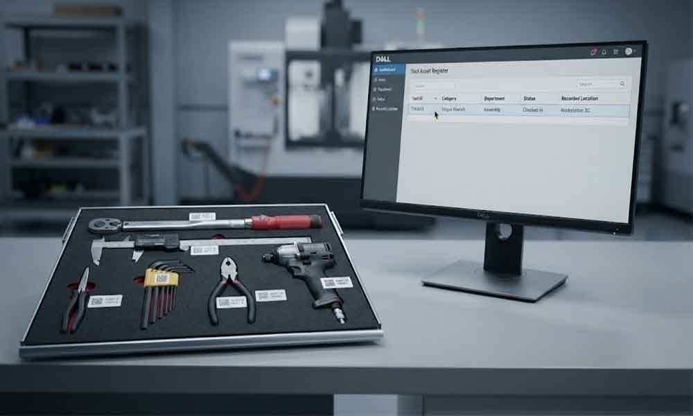
Photo shared by cykeo6688: Industrial tools are assets, even when they are too small to appear on a company’s main equipment re
CY
cykeo6688@cykeo6688· Monday at 9:25 AM

what is a rfid label: A Practical Guide to RFID Labels

RFID label is a printable identification label that combines an RFID chip and antenna with a paper or synthetic label material. It allows products, cartons, or assets to be identified wirelessly while retaining human-readable information such as product names, numbers, or barcodes. That distinction matters in real deployments. An RFID label is not simply a barcode with radio communication added. Inside the label is an RFID inlay containing the chip and antenna; the outer material provides the surface for printing and attachment. At Cykeo, when we evaluate RFID labels for an application, we look at the item being tagged first, not just the reader specification. A label that performs well on corrugated cartons may behave very differently when moved onto a metal tool, liquid-filled container, or densely packed product. That is one of the details that tends to get missed during procurement. How RFID Labels Work What Is Inside an RFID Label? A typical RFID label contains three functional layers: Component Primary Function RFID chip Stores identification and other encoded data RFID Antenna Receives reader energy and communicates with the reader Label substrate Holds the inlay and provides a printable surface For a passive RFID label, the tag does not need a battery. The reader supplies the RF energy needed for communication. GS1 describes RFID as a family of technologies in which information is stored in a microelectronic chip and communicated with dedicated readers using radio-frequency waves or fields. GS1’s current standards repository lists EPC Gen2 as the UHF RFID air-interface standard and the current version as 3.0.1, modified February 26, 2026. That makes RFID labels particularly useful when a business needs to identify large numbers of physical objects without manually scanning every printed code. What Data Can an RFID Label Carry? The answer depends on the RFID chip and how the system is configured. In an EPC-based deployment, an RFID label can carry an Electronic Product Code associated with a unique physical object. GS1 explains that EPC provides a way to encode GS1 identifiers on RAIN RFID tags and can add serialization to identifiers such as GTINs. Typical information associated with an RFID label includes: Product identification Serialized item information Asset identification Inventory references Application-specific user memory Information associated with a GS1 identifier The label does not necessarily need to contain every piece of product information. In many systems, the RFID tag provides the identifier while the business database holds the detailed record. RFID Label Types for Different Applications UHF RFID Labels UHF RFID labels are common in logistics, warehousing, retail, and supply-chain applications because they can support identification of multiple tagged objects within a reading zone. GS1’s EPC/RFID specifications identify UHF EPC/RFID as operating in the 860–960 MHz range, while the specific regulatory operating band depends on the region. For a warehouse carton, a conventional UHF RFID label may be sufficient. For metal assets, however, a standard paper label is often not the right choice. A specialized on-metal RFID label may be required because the mounting surface changes antenna behavior. Paper RFID Labels vs Industrial RFID Tags Type Typical Environment Main Consideration Paper RFID label Cartons, products, packaging Low-cost labeling Synthetic RFID label More demanding environments Improved material durability On-metal RFID label Metal equipment and tools Designed for metal surfaces Hard RFID tag Industrial assets Mechanical protection The physical format should follow the application. It is tempting to standardize on one label across an entire operation, but that can create unnecessary read-performance problems later. UHF RFID label attached to a cardboard shipping carton in a European warehouse A printable UHF RFID label combines product identification with wireless RFID tracking. What Are RFID Labels Used For? RFID Label Applications in Supply Chains RFID labels are useful wherever physical products need to be identified as they move through a process. Common applications include: Warehouse inventory: identifying cartons, cases, and products Retail: supporting item-level inventory visibility Manufacturing: tracking components and work-in-progress Logistics: associating shipments with digital records Libraries: identifying books and other circulating assets Asset management: assigning unique identities to equipment GS1’s traceability guidance specifically describes EPC/RFID tags being used for serialized identification and notes that fixed readers and handheld devices can be combined to capture important tracking events. That combination is important. A label on its own does not create traceability. The reader, software, business identifier, and capture points all have to work together. What Makes an RFID Label Useful? The practical advantage becomes clearer when looking at a busy receiving area. A barcode requires the operator or scanning equipment to optically capture the printed symbol. RFID can identify tagged objects through radio communication, potentially allowing several tags to be captured in one reading operation. Research from Auburn University’s RFID Lab illustrates why that capability matters. A field experiment involving 13 retail stores over 23 weeks found that RFID-enabled automatic inventory-record adjustment reduced inventory record inaccuracy by about 26%. The researchers also conducted a larger second study involving 62 stores and five product categories. That result should not be interpreted as a guaranteed 26% improvement for every RFID installation. Product category, process design, reader placement, tag performance, and operational discipline all matter. The more useful lesson is that RFID labels can become part of a measurable inventory-control process rather than functioning merely as another identification sticker. What Should You Check Before Buying RFID Labels? Before ordering a large quantity, I recommend testing actual samples against the actual products. Check: Tag frequency — confirm compatibility with the RFID reader. Chip type and memory — verify the required data can be stored. Mounting surface — test cardboard, plastic, metal, glass, or other materials. Label dimensions — make sure the label fits the available surface. Printing requirements — determine whether barcodes, text, or logos must also appear. Read performance — test at the real installation distance and orientation. Environmental conditions — consider moisture, temperature, abrasion, and handling. The last three are frequently overlooked. In an actual warehouse, labels are bent, covered, stacked, exposed to dust, and sometimes placed at inconsistent orientations. That is where a specification sheet stops being enough. RFID Label vs Barcode: What Is the Difference? Why Use an RFID Label Instead of a Barcode? An RFID label and a barcode label can look similar on the outside, but they operate differently. A barcode stores information visually and normally requires a scanner to see the printed code. An RFID label stores information electronically in its RFID chip and communicates wirelessly with an RFID reader. Feature RFID Label Barcode Label Reading method Radio frequency Optical scanning Line of sight Not necessarily required Generally required Multiple-item reading Possible Usually one code at a time Data storage RFID chip memory Printed symbol Rewritable Depending on chip No Human-readable printing Yes Yes Typical application Automated identification Conventional identification This does not mean RFID labels automatically replace barcodes. In many deployments, the two are printed together. That combination is useful. The RFID component supports automated machine reading, while the barcode gives employees a familiar visual reference during exception handling. How to Choose the Right RFID Label Match the RFID Label to the Tagged Object The correct RFID label depends heavily on the object receiving it. A few practical examples: Cardboard carton: A standard passive UHF RFID label is often suitable because cardboard has relatively little influence on UHF tag performance. Plastic container: Testing is still important because container geometry and contents can affect the RF environment. Metal tool: A conventional paper RFID label may perform poorly when directly attached to metal. An on-metal RFID label designed with an appropriate structure is usually a better starting point. Liquid-filled container: The liquid content can affect UHF RFID performance, so the tag should be tested on the actual container rather than evaluated separately. At Cykeo, I prefer testing the complete combination—tag + product + reader + antenna + software workflow—before recommending a production quantity. It takes longer at the beginning, but it avoids the expensive situation where thousands of labels have already been printed and the reading process then needs to be redesigned. What Is the Read Range of an RFID Label? RFID Label Reading Distance Depends on the System There is no single reading distance that applies to every RFID label. Actual performance depends on: RFID frequency Reader output power Antenna gain and polarization RFID chip sensitivity Label orientation Distance between reader and tag Tagged material Nearby metal or liquids Regional radio regulations For UHF systems, GS1 specifies the EPC Gen2 air interface within the 860–960 MHz frequency range, but a deployment does not simply operate at one universal frequency worldwide. Regional spectrum rules determine the permitted operating channels and power conditions. This is why I would not select an RFID label based solely on a supplier’s advertised maximum distance. A controlled three-meter reading zone can be much more useful than an uncontrolled ten-meter zone if the business needs to know exactly when a pallet enters a specific area. How RFID Labels Fit Into a Complete RFID System RFID Label, Reader, Antenna, and Software An RFID label is only one part of an RFID system. A typical deployment contains: RFID label → RFID reader → antenna → communication interface → application software → business database Each layer has a different job. The label identifies the object. The reader communicates with the label. The antenna shapes the RF interaction. The software interprets the captured information. The business system turns the event into an inventory, shipment, asset, or production record. That last step is where many projects become complicated. A warehouse can capture thousands of EPC values every hour, but those readings have little operational value if the software cannot distinguish receiving, storage, picking, and shipping events. RFID labeled cartons moving through an automated European distribution center RFID labels allow tagged products and cartons to become identifiable data points within automated inventory processes. What Are the Benefits of RFID Labels? Practical Advantages for Businesses RFID labels can provide several operational advantages when the application is properly designed: Automatic identification of tagged objects Reduced manual scanning for repetitive inventory operations Serialized identification at item level Potential multi-tag reading with compatible systems Printable information for human operators Integration with inventory and enterprise systems Flexible label formats for different products and environments The important qualification is “when properly designed.” RFID does not remove the need for process engineering. A poorly positioned antenna, unsuitable tag, excessive read zone, or badly configured software can create just as many operational problems as it solves. That is why field testing matters. Frequently Asked Questions About What Is a RFID Label 1. What is a RFID label used for? A RFID label is used to identify and track products, cartons, assets, and other physical objects wirelessly. It is commonly used in inventory management, logistics, manufacturing, retail, libraries, and supply-chain operations. 2. How does a RFID label work? A passive RFID label receives RF energy from a compatible reader and uses that energy to communicate information stored in its RFID chip. The reader captures the tag data and sends it to connected software. 3. Is a RFID label the same as a barcode? No. A barcode stores information in a visual printed pattern, while an RFID label contains an electronic RFID inlay. RFID can support wireless and multi-tag identification, while barcode scanning normally requires optical access to the printed code. 4. Can RFID labels be printed? Yes. Many RFID labels have a printable surface that can contain product names, serial numbers, barcodes, logos, or other human-readable information while the embedded RFID inlay provides wireless identification. 5. Can RFID labels be used on metal? Some can, but a standard RFID label should not automatically be assumed to work well directly on metal. Specialized on-metal RFID labels are designed for these applications and should be tested on the actual asset. 6. Are RFID labels reusable? It depends on the label construction and application. Some RFID chips can be rewritten, but adhesive labels are generally designed around the lifecycle of the item or packaging to which they are attached. Practical RFID Label Testing at Cykeo When testing a new RFID label, I would not begin with a theoretical maximum range. I start with the actual object. Place the label where it will really be attached. Put several tagged objects into the same carton or shelf configuration. Introduce the reader and antenna that will actually be installed. Then repeat the test while changing orientation, distance, tag density, and movement speed. This reveals problems that a bench test can hide. For example, a label may read perfectly when placed flat and centered. Turn the carton ninety degrees, add ten more cartons, move them through the reading zone, and the result can change. That is not necessarily a defective label. It is information about the RF environment. This is also why Cykeo treats RFID labels as part of the complete identification system rather than as an isolated consumable. Conclusion What is a RFID label? It is a printable RFID identification medium that combines an RFID inlay with a label substrate, allowing physical objects to carry both visible information and electronically readable identity. For straightforward cardboard packaging, a conventional UHF RFID label may be enough. Metal, liquids, harsh environments, or specialized asset tracking require more careful tag selection and testing. The useful question is therefore not simply which RFID label has the longest advertised range. It is which label remains readable, writable when required, physically suitable, and operationally useful throughout the actual workflow. That distinction is where successful RFID implementation begins. https://www.cykeorfid.com/rfid-product/rfid-tags/

Photo shared by cykeo6688: RFID label is a printable identification label that combines an RFID chip and antenna with a paper o
CY
cykeo6688@cykeo6688· October 10 at 8:46 AM

RFID Tool Cabinet Data Management: Building Clean and Reliable Tool Records

Standardizing Tool Data Fields Tool records should use consistent field definitions. For example, one system should not use: Department while another uses: Dept. and a third uses: Responsible Area for exactly the same concept without a defined mapping. Common fields may include: Tool ID RFID ID Tool Category Department Location Status User ID Cabinet ID This supports cleaner reporting and easier software integration. For a broader standardization strategy, see RFID Tool Cabinet for Tool Standardization. Managing Duplicate Tool Records Duplicate records can appear during migration or manual data entry. For example: TW-00125 and Torque-125 may represent the same physical tool. If both remain active, the organization may see incorrect inventory totals. A data cleaning process should identify: Duplicate tool IDs Duplicate serial numbers Duplicate RFID tags Similar tool names Old inactive records Retired records incorrectly marked active Duplicates should be resolved before large-scale RFID deployment. RFID Tag Replacement RFID tags can eventually become damaged or unreadable. A replacement process should preserve the existing tool identity. For example: Old RFID Tag → Tool ID TW-00125 → Retired Tag then: New RFID Tag → Tool ID TW-00125 → Active Tag The tool’s historical transactions should remain associated with the tool. This is especially important for tools with maintenance, calibration, or quality records. Managing Tool Status Data Tool status should be updated consistently. A practical status structure might include: Available Checked Out In Use Return Pending Inspection Required Maintenance Calibration Required Restricted Retired The exact terminology can vary. The important point is that every status should have a clear definition. For example, “Unavailable” could mean: Under repair Missing Reserved Calibration expired Restricted If these situations are operationally different, they may need separate status or reason fields. https://www.cykeorfid.com/rfid-product/rfid-smart-cabinet/rfid-tool-cabinet/
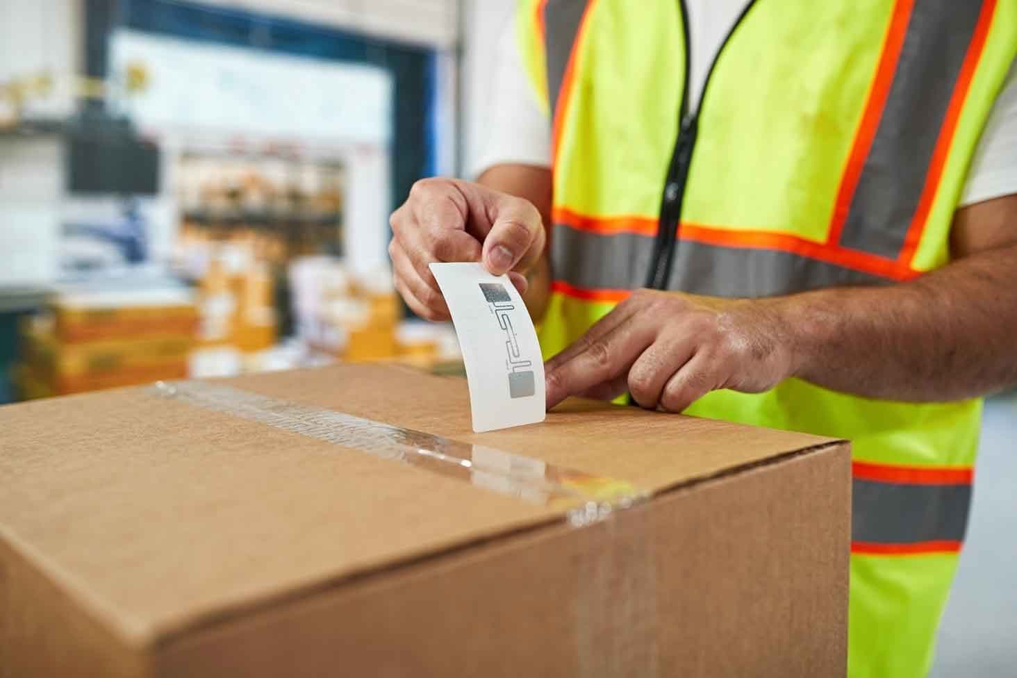
Photo shared by cykeo6688: Standardizing Tool Data Fields
Tool records should use consistent field definitions.

For example
CY
cykeo6688@cykeo6688· October 9 at 8:00 AM

RFID Tool Cabinet for Tool Lifecycle Management: Managing Tools From Registration to Retirement

What Is Tool Lifecycle Management? Tool lifecycle management means managing a tool through the different stages of its working life. A typical lifecycle may look like: Purchase → Registration → RFID Tagging → Storage → Issue → Use → Inspection → Maintenance → Calibration → Return to Service → Retirement Not every tool will pass through every stage. For example, a simple hand tool may require only registration, issue, return, inspection, and retirement. A precision measuring instrument may require much more information, including calibration certificates, inspection results, service history, and restricted-use rules. The lifecycle should therefore be designed around the actual tool category. Tool lifecycle from registration and storage to maintenance, calibration and retirement Stage 1: Tool Registration The lifecycle starts when the tool enters the organization. The digital record may include: Tool ID Tool name Manufacturer information Model Specification Purchase date Supplier Department Tool category Ownership RFID tag ID Calibration requirement Maintenance requirement The RFID tag connects the physical tool to this record. This is important because two tools can look almost identical while having completely different service histories. A unique tool ID helps prevent these records from being mixed. Stage 2: RFID Tagging and Identification The RFID tag should be selected according to the tool’s physical characteristics. Metal surfaces, curved surfaces, small tools, high-temperature environments, chemicals, and frequent handling can all affect tag selection. A tag that works well on one tool may not perform the same way on another. For this reason, organizations should test representative tools before applying tags to the entire tool population. The objective is not simply to attach an RFID label. The objective is to create a stable relationship between: Physical Tool ↔ RFID Identity ↔ Digital Tool Record Stage 3: Storage and Availability After registration, tools may be placed inside an RFID smart tool cabinet or another controlled storage location. The system can associate the tool with: Cabinet Shelf or position Department Location Availability Current status This gives employees a more useful view than simply seeing a physical storage cabinet. For example, a tool may exist in the inventory database but still be unavailable because it is undergoing calibration. The system should distinguish between inventory existence and actual availability. See our guide to RFID Tool Cabinet Tool Reservation and Availability Management for more information. Stage 4: Tool Issuing and Daily Use Once a technician needs the tool, the normal workflow may include user authentication, tool identification, checkout, and work assignment. The RFID cabinet can record the transaction and update the tool’s status. A simplified lifecycle event might look like: Available → Checked Out → In Use The tool can remain associated with the responsible user until it is returned or transferred according to the organization’s workflow. This information becomes especially useful when tools are shared between multiple employees or departments. For the issuing process, see RFID Tool Issuing and Return Management. Stage 5: Inspection After Use A tool may look physically normal while still requiring inspection. Depending on the tool type, inspection can check: Physical damage Wear Missing components Cleanliness Function Calibration status Safety condition After return, the system may allow a supervisor or technician to change the tool status. For example: Returned → Inspection Required → Available or: Returned → Damaged → Maintenance Required This separates tool return from tool readiness. That distinction is important in industrial environments. Stage 6: Maintenance and Repair Tools eventually require maintenance. A tool may be removed from normal circulation and assigned a maintenance status. Possible states include: Maintenance Required Under Repair Waiting for Parts Inspection Required Ready for Service Retired The RFID cabinet provides the tool identity, while management software can store the maintenance information. This allows maintenance records to stay connected with the physical tool. See RFID Tool Cabinet Maintenance and Troubleshooting for related maintenance workflows. Stage 7: Calibration Management Precision tools may require periodic calibration. A tool’s lifecycle record can include: Last calibration date Next calibration date Calibration result Certificate number Calibration provider Calibration status When the calibration period expires, the tool can be changed to a restricted or unavailable status. This can help prevent an overdue tool from being treated as normally available. RFID does not replace the calibration process. It helps connect the physical tool with the relevant digital status. See RFID Tool Cabinet for Tool Calibration for the dedicated calibration workflow. Stage 8: Return to Service After maintenance, inspection, or calibration, the tool should not automatically become available. A controlled workflow may require: Service Complete → Inspection → Approval → Available The exact approval process depends on the tool and organization. For critical equipment, a supervisor or quality team may need to confirm that the tool can return to production. This creates a clear boundary between a tool that has been serviced and a tool that has actually been approved for use. Stage 9: Tool Retirement Eventually, every tool reaches the end of its useful life. Reasons can include: Excessive wear Physical damage Obsolete specification Failed inspection Repeated repair High maintenance cost Replacement by a newer model Production process changes The tool should be marked as retired rather than simply deleted from the database. A retired record may still contain useful historical information. For example, management may later need to know: When the tool was purchased How long it was used How often it required repair How many calibration cycles it completed Why it was retired This information can support future purchasing and asset decisions. Tool Lifecycle Status Management A practical RFID tool management system should define clear statuses. RFID software showing available, checked out, maintenance and calibration tool statuses A possible structure is: Lifecycle Stage Example Status New New / Unregistered Registered Active Inventory Available Ready for Use Issued Checked Out In Use Assigned Returned Return Pending Inspection Inspection Required Maintenance Under Maintenance Calibration Calibration Required Restricted Not Available Approved Ready for Service Retired Retired The exact names should be adapted to the organization’s workflow. Too many statuses can make the system difficult for employees to understand. Too few statuses can hide important differences between available, damaged, calibrated, and restricted tools. Connecting Lifecycle Data With Software An RFID cabinet is most useful when it works with the wider management system. Depending on the organization, lifecycle information may connect with: ERP MES WMS CMMS Asset management software Calibration software Quality systems Custom applications For example: RFID Cabinet → Tool Event → Software → Tool Status → User / Work Order / Maintenance Record This can turn a cabinet transaction into a useful business event. See RFID Tool Cabinet Software Integration for more information about APIs, data mapping, and system integration. Lifecycle Management Across Multiple Locations Tools can move between departments during their working life. A tool may start in: Central Tool Room then move to: Maintenance Department → Production Line → Inspection Area → Tool Room When multiple RFID cabinets share the same tool database, these location changes can remain connected to the same tool identity. This becomes especially useful when an organization operates multiple production areas or facilities. See RFID Tool Cabinet for Multi-Location Tool Management for more information. Why Lifecycle Management Is Different From Inventory Management Inventory management mainly asks: “What tools do we have?” Lifecycle management asks: “What stage is each tool in, and what should happen next?” For example, two identical torque tools may both exist in inventory. But: Tool A is available. Tool B is overdue for calibration. Inventory counting alone may treat both as available assets. Lifecycle management distinguishes their operational status. This is one reason lifecycle data can become more useful than simple inventory totals. Practical Implementation Workflow A practical project can follow these steps: 1. Classify tool types Separate general hand tools, precision tools, high-value tools, specialized equipment, and other categories. 2. Define lifecycle stages Document what happens from tool registration through retirement. 3. Create unique IDs Make sure every managed tool has one clear digital identity. 4. Select RFID tags Test tag performance on representative tools. 5. Define status rules Specify who can change a tool from available to maintenance, calibration, restricted, or retired. 6. Configure cabinet workflows Connect RFID identification with checkout, return, inventory, and status changes. 7. Connect software Map tool events to ERP, MES, CMMS, calibration, or custom systems where required. 8. Test real scenarios Test normal use, damaged returns, calibration expiry, maintenance, missing tools, and retirement. 9. Train employees Users should understand what each tool status means and what action is required. 10. Review lifecycle data After deployment, review whether the system is producing useful information rather than unnecessary records. Common Mistakes in Tool Lifecycle Management Treating Every Tool the Same A screwdriver and a precision measuring instrument may need completely different lifecycle rules. Deleting Retired Tools Retirement should normally close the lifecycle rather than erase the historical record. Using Too Many Statuses Complex status systems can confuse employees and reduce adoption. Ignoring Maintenance Data Tool lifecycle management becomes less useful when maintenance events are kept outside the main tool record. Skipping RFID Tag Testing Tags should be tested on actual tools and in the real cabinet environment. Automating Before Defining the Workflow RFID hardware cannot fix an unclear lifecycle process. Tool Lifecycle Management Checklist Before deployment, confirm: Tool categories are defined Unique tool IDs are available RFID tags are tested Lifecycle stages are documented Tool statuses are clear User permissions are defined Checkout rules are documented Return inspection is defined Maintenance workflow is defined Calibration workflow is defined Retirement rules are defined Software integration is tested Historical records are retained Users are trained Acceptance criteria are documented FAQs 1. What is RFID tool lifecycle management? It is the management of a tool from registration and storage through use, inspection, maintenance, calibration, and eventual retirement, using RFID identification and connected software. 2. Can an RFID cabinet manage tool maintenance status? Yes. RFID identifies the tool, while connected software can store maintenance status and update availability according to the organization’s workflow. 3. Can retired tools remain in the system? Yes. Keeping retired records can preserve purchase, usage, maintenance, calibration, and retirement history for future reference. 4. Does every tool need the same lifecycle? No. Lifecycle rules should match the tool category. Precision and regulated tools may require more inspection and calibration stages than basic hand tools. 5. Can lifecycle management connect with a CMMS? Yes. An RFID cabinet can provide tool identification and transaction events that may be integrated with a CMMS through the available software interface. https://www.cykeorfid.com/rfid-product/rfid-smart-cabinet/rfid-tool-cabinet/
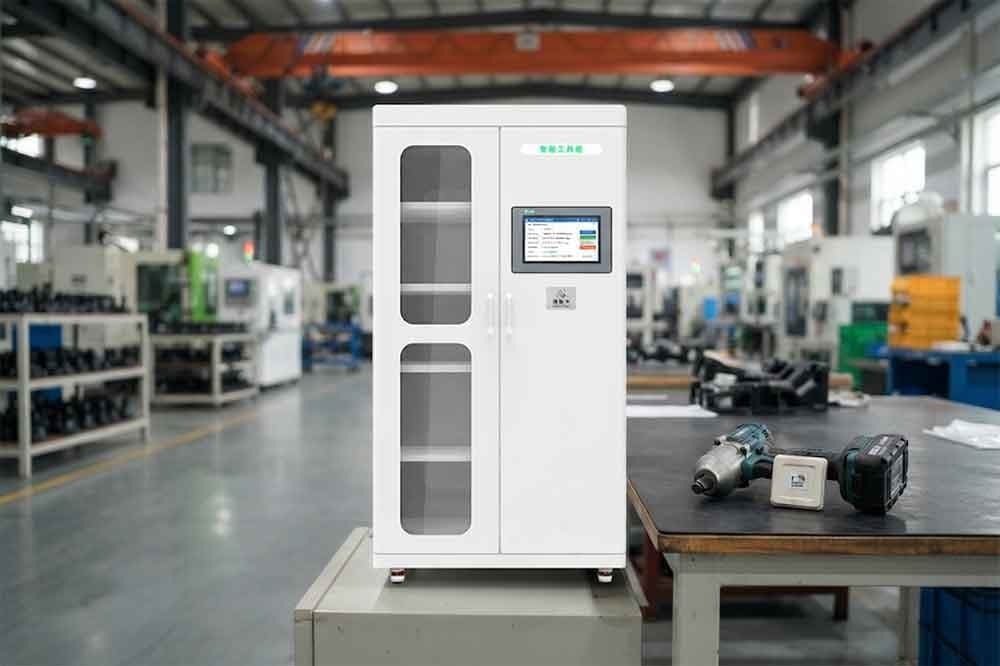
Photo shared by cykeo6688: What Is Tool Lifecycle Management?
Tool lifecycle management means managing a tool through the diff
CY
cykeo6688@cykeo6688· October 8 at 6:18 AM

what does a handheld rfid writer do

A handheld RFID writer writes, updates, and manages data stored on RFID tags through wireless communication. It allows operators to encode tag information, verify stored data, and perform mobile RFID management tasks without connecting tags to fixed equipment. Understanding What a Handheld RFID Writer Does in Real Applications When companies ask what does a handheld rfid writer do, they are usually looking for its practical role in daily operations rather than only a technical definition. A handheld RFID writer is a portable device that combines RFID reading and writing functions, allowing users to identify tags, encode information, modify stored data, and verify tag status directly at the working location. Unlike a standard RFID reader that mainly collects tag information, a handheld RFID writer can communicate with writable RFID tags and change their stored data when required. This makes it valuable in environments where tags are applied to moving assets, inventory items, tools, production materials, or reusable containers. In my experience working with RFID deployment projects, one common misunderstanding is assuming tag writing only happens during initial labeling. In actual factories and warehouses, tag information often changes. Products move between locations, assets are reassigned, and inventory records need updates. A handheld RFID writer reduces the need to bring every tagged item back to a workstation. For example, during a warehouse setup, operators may need to attach RFID tags to hundreds of storage items. Carrying products back to a desktop encoding station creates unnecessary movement. A handheld RFID writer allows workers to stay near the inventory area, write required information, immediately verify the tag response, and continue the process. This practical workflow is why handheld RFID writers are widely used in asset management, logistics, manufacturing, and field service applications. How a Handheld RFID Writer Works RFID Reading and Writing Communication Process A handheld RFID writer communicates with tags through radio frequency signals. The device contains an RFID module, antenna system, processor, and communication interface that work together to exchange information with RFID tags. The basic process includes: The operator selects or scans the target RFID tag. The handheld writer sends radio signals to establish communication. The device writes new information into the available tag memory area. The system reads back the stored data for verification. The updated information is transferred to business software if required. The writing process depends on the RFID frequency and tag standard. For industrial applications, UHF RFID handheld writers commonly support EPC Class 1 Gen 2 / ISO 18000-63 compatible tags, which are widely used for supply chain identification. According to GS1, EPC-based RFID technology provides standardized identification methods for products and assets across global supply chains. This standardization helps companies connect RFID data between different operational systems. What Information Can a Handheld RFID Writer Store? Writing Data Into RFID Tag Memory A handheld RFID writer does not simply “activate” a tag. It interacts with specific memory areas inside the RFID chip. Depending on the tag type, information may include: RFID Memory Area Purpose EPC Memory Stores electronic product identification information User Memory Stores additional customized business data TID Memory Contains unique chip identification information Reserved Memory Used for security-related functions such as passwords In industrial environments, companies usually avoid writing unnecessary information into tags. A common approach is storing a unique identifier on the tag and linking detailed product information through enterprise software. This method keeps tag memory management simple while allowing businesses to update product records through databases. Why Businesses Use Handheld RFID Writers A handheld RFID writer provides flexibility that fixed RFID equipment cannot always offer. Key advantages include: 1. Mobile RFID Tag Programming Workers can write tags directly where products, tools, or assets are located. Typical examples: Manufacturing floor labeling Warehouse inventory preparation Equipment identification Returnable container management 2. Faster Field Operations A portable RFID writer reduces repeated transportation between operating areas and desktop stations. In practical deployments, saving several seconds per tag can create noticeable improvements when thousands of tags require programming. 3. Immediate Tag Verification Writing data without verification creates risks. A handheld RFID writer allows operators to confirm whether the tag received the correct information before the item enters the next workflow. Handheld RFID Writer Applications in Different Industries Warehouse and Logistics Warehouses use handheld RFID writers when inventory labels need to be created or updated on-site. Common examples include: Pallet identification Carton labeling Storage location management Shipment preparation Instead of moving products to a fixed encoding station, workers can complete RFID programming directly in the warehouse area. Manufacturing and Industrial Asset Tracking Manufacturing environments often require RFID tags on tools, components, and equipment. A handheld RFID writer helps engineers: Assign new asset IDs Update maintenance information Replace damaged tags Verify existing tag data During industrial RFID testing, I have found that the writing process itself is rarely the difficult part. The challenge is making sure the written information matches the company’s actual workflow. A tag with incorrect data can create confusion throughout an entire tracking system. Warehouse worker using handheld RFID writer to encode RFID tags on inventory items A warehouse operator uses a portable RFID writer to program and verify tagged inventory directly on-site. Handheld RFID Writer vs Traditional RFID Reader Although both devices communicate with RFID tags, their functions are different. Feature Handheld RFID Writer Traditional RFID Reader Read RFID Tags Yes Yes Write Tag Data Yes Usually limited or unavailable Mobile Operation Yes Depends on model Field Programming Suitable Usually not designed for it Asset Updating Suitable Mainly identification A handheld RFID writer is designed for situations where RFID data needs to be created, modified, or maintained outside a fixed workstation. How to Choose the Right Handheld RFID Writer for Business Use Selecting a handheld RFID writer requires more consideration than simply checking reading distance or output power. In real projects, the right device depends on tag type, working environment, communication requirements, and the purpose of writing data. Before choosing equipment, companies should evaluate several factors: Selection Factor Why It Matters RFID Frequency Support Determines compatible tags and application scenarios Writing Distance Affects operation efficiency in the field Tag Compatibility Ensures reliable communication with existing RFID labels Software Integration Allows data exchange with business systems Battery Performance Influences mobile working time For example, a warehouse employee programming hundreds of pallet tags has different requirements from a maintenance engineer updating equipment identification information inside a factory. A device optimized for office environments may not perform well in industrial conditions. Dust, metal surfaces, crowded storage areas, and electromagnetic interference can all influence RFID communication. This is why professional RFID deployment usually begins with application testing rather than purchasing equipment based only on specifications. Cykeo Handheld RFID Writer Solutions for Practical RFID Deployment At Cykeo, RFID solutions are developed around real operational requirements. Through years of working with RFID hardware integration, our engineers have focused on improving the connection between RFID equipment and daily business processes. A handheld RFID writer solution typically needs to support: Stable communication with UHF RFID tags Fast tag identification and data writing Reliable verification after programming Integration with inventory or asset management software Flexible operation in warehouses, factories, and field environments In practical deployments, the writing function is only one part of the workflow. The complete process includes tag preparation, data management, verification, and system synchronization. For example, when a company introduces RFID tags for tool management, the operator may need to: Assign a unique equipment number. Write identification data into the RFID tag. Confirm successful programming. Link the tag record with maintenance software. Track future movement and usage history. The handheld RFID writer becomes the bridge between physical equipment and digital records. Common Problems When Using a Handheld RFID Writer Why RFID Tags Sometimes Fail During Writing A failed writing process does not always mean the RFID writer has a problem. In field applications, several factors can affect performance. Common causes include: Incorrect Tag Selection Different RFID tags are designed for different materials and environments. A standard label tag may not perform well when attached directly to metal equipment. Insufficient Tag Positioning The relationship between the handheld writer antenna and the tag antenna affects communication quality. Small changes in angle or distance may influence writing stability. Incorrect Memory Configuration RFID tags contain different memory areas. Writing information into the wrong area or exceeding available memory capacity can cause errors. Environmental Interference Industrial environments may contain metal structures, machinery, and other RF signals that influence RFID communication. During RFID testing projects, engineers often spend more time adjusting the application environment than changing the hardware. A reliable RFID system depends on correct configuration, not just powerful equipment. Handheld RFID Writer Applications Beyond Inventory Management Many people associate RFID writers only with inventory labeling, but modern applications are much broader. Tool Tracking Factories can attach RFID tags to tools and use handheld RFID writers to create digital identities for equipment. Workers can update: Tool ownership information Maintenance records Inspection status Usage history Healthcare Equipment Management Hospitals use RFID systems to manage medical equipment and reusable assets. A handheld RFID writer can help staff: Register new equipment Replace damaged tags Update asset information Retail Product Management Retail businesses can use handheld RFID writers during product preparation, inventory organization, and store operations. Tags can be programmed before products enter shelves, helping connect physical goods with digital inventory systems. Engineer using handheld RFID writer to update RFID tagged equipment in factory A factory engineer uses a handheld RFID writer to maintain digital records of industrial assets. Frequently Asked Questions About Handheld RFID Writers 1. What does a handheld RFID writer do? A handheld RFID writer reads and writes information stored on RFID tags. It allows operators to program new tags, update existing tag data, and verify information directly in warehouses, factories, and field environments without moving items to fixed equipment. 2. Can a handheld RFID writer read RFID tags? Yes. Most handheld RFID writers also include RFID reading functions. This allows users to identify tags before writing data and confirm whether the information has been stored correctly after programming. 3. What types of RFID tags can a handheld RFID writer program? The compatible tags depend on the device frequency and supported RFID standards. Many industrial handheld RFID writers support UHF RFID tags based on EPC Class 1 Gen 2 / ISO 18000-63 standards. 4. What industries use handheld RFID writers? Handheld RFID writers are used in manufacturing, logistics, retail, healthcare, warehouse management, and asset tracking. They are especially useful when RFID tags need to be created or updated away from fixed workstations. 5. What is the difference between a handheld RFID writer and a desktop RFID writer? A desktop RFID writer is usually installed at a fixed location for controlled tag encoding. A handheld RFID writer provides mobility, allowing workers to program and verify tags directly where assets or products are located. 6. Can RFID tag data be rewritten? Many RFID tags support rewriting depending on their chip design and memory configuration. Organizations often rewrite tags when updating asset information, changing inventory records, or reusing returnable containers. 7. Does a handheld RFID writer require software? Yes. Most professional applications use software or APIs to manage tag data, connect with databases, and synchronize RFID information with existing business systems. Final Thoughts: Understanding What a Handheld RFID Writer Does When exploring what does a handheld rfid writer do, the answer is not limited to writing information into RFID tags. It is a mobile tool that helps businesses create, update, and maintain accurate digital identities for physical objects. From warehouse inventory preparation to industrial asset management, handheld RFID writers make RFID operations more flexible by bringing tag programming directly into the working environment. At Cykeo, RFID solutions are designed around practical deployment challenges, including tag compatibility, workflow integration, and real operating conditions. A reliable handheld RFID writer is not only a programming device but also an important connection between physical assets and digital management systems. https://www.cykeorfid.com/rfid-product/rfid-readers/

Photo shared by cykeo6688: A handheld RFID writer writes, updates, and manages data stored on RFID tags through wireless commun
CY
cykeo6688@cykeo6688· September 30 at 2:25 AM

RFID Tool Cabinet for High-Value Tools: Tracking, Access Control, and Accountability

RFID Tool Cabinet vs. Manual High-Value Tool Control Manual control can work in small operations with few tools and limited users. However, manual methods may become difficult when: Tool quantities increase Multiple shifts share tools Several departments use the same tools Tools move frequently Audit requirements increase Calibration information must be tracked Managers need historical transaction data An RFID cabinet provides automated identification and digital records, but it also requires appropriate hardware, software, tagging, and implementation. The right approach depends on the organization’s actual requirements. 16. Choosing an RFID Cabinet for High-Value Tools When selecting a cabinet, consider: Tool characteristics Measure tool dimensions, materials, weight, and tag mounting locations. Storage structure Decide whether shelves, drawers, compartments, or mixed storage are required. Access control Determine whether every tool should have the same permission level. RFID performance Test actual tools rather than relying only on theoretical reading specifications. Software Check whether the system can record users, transactions, tool status, and audit history. Integration Consider ERP, MES, WMS, CMMS, or custom software requirements. Environment Evaluate dust, temperature, moisture, vibration, and other industrial conditions. Expansion Consider whether additional cabinets or departments may be added later. 17. Start With a Controlled Pilot For high-value tools, a pilot deployment can be useful before a full rollout. A practical pilot might include: One RFID tool cabinet 20–50 selected tools Several authorized users One department Real maintenance or production tasks Test: Tool identification User authentication Checkout Return Unauthorized access Inventory Calibration status Reporting Software integration The pilot provides actual operational data before the organization expands the system. Conclusion High-value tools require more than simple storage. Organizations need to know where critical tools are, who accessed them, when they were removed, whether they were returned, and whether they remain suitable for use. An RFID tool cabinet can connect individual tools with user authentication, access permissions, transaction history, inventory records, calibration information, and enterprise software. The most effective implementation starts with the actual tools and workflow. Tag performance, cabinet layout, user permissions, software integration, and audit requirements should all be tested before large-scale deployment. For organizations managing expensive, specialized, or operationally critical tools, RFID can provide a structured foundation for more accountable tool management. For organizations managing many shared tools, RFID tool tracking can provide individual identification and a clearer record of tool movement. A controlled RFID tool checkout system can then connect the employee with the specific high-value tool being removed from storage. Companies with broader access-control requirements can also use an RFID tool control system to manage permissions for restricted tools and departments. For enterprise projects, RFID Tool Cabinet Software Integration can connect tool transactions with maintenance, production, inventory, or employee systems. Frequently Asked Questions 1. Can RFID track expensive tools? Yes. Each tool can receive a unique RFID tag and be associated with its own digital record, allowing the system to track checkout, return, location, user, and status information. 2. Can an RFID cabinet restrict tool access? Yes. User authentication and permission rules can be configured so that specific employees or departments can access selected tools. 3. Can RFID track calibrated tools? Yes. The software can associate tools with calibration information and status. Organizations can define rules for tools that are due for calibration or have expired calibration. 4. Can RFID connect tools with work orders? Yes. Through software integration, tool checkout and return events can potentially be associated with CMMS work orders or other maintenance systems. 5. Is RFID necessary for every expensive tool? Not necessarily. RFID is more useful when tools are frequently shared, difficult to track manually, operationally important, or subject to access and audit requirements.

Photo shared by cykeo6688: RFID Tool Cabinet vs. Manual High-Value Tool Control
Manual control can work in small operations wi
CY
cykeo6688@cykeo6688· September 29 at 5:44 AM

RFID Tool Cabinet Software Integration: How to Connect RFID Tool Management Systems

RFID tool cabinet can automatically identify tools, but identification alone does not create a complete tool management system. For industrial applications, RFID events often need to move from the cabinet to management software, where they can be connected with employees, tool records, work orders, inventory, maintenance schedules, and other business data. That is where software integration becomes important. A well-designed RFID tool cabinet system can act as a data collection point between physical tools and an organization’s existing digital systems. 1. What Is RFID Tool Cabinet Software Integration?​ RFID tool cabinet software integration connects the cabinet’s RFID hardware and tool management application with other software platforms. A simplified data flow looks like this: RFID Tag → RFID Reader → Cabinet Software → API → Business System The RFID reader identifies a tagged tool. The cabinet software processes the event and associates the RFID tag with a tool record. The system can then send relevant information to another platform. Depending on the project, the transferred information may include: Tool ID RFID tag ID User ID Cabinet ID Storage position Check-out time Return time Tool status Access event Inventory event Work-order reference The exact data structure depends on the customer’s software architecture. RFID tool cabinet system architecture from tags to enterprise software Conclusion​ RFID tool cabinet software integration connects physical tool activity with the digital systems already used by an organization. The most important work happens before coding: defining data ownership, mapping tool and user identifiers, deciding which RFID events matter, selecting real-time or scheduled synchronization, and planning error handling. For industrial projects, a well-designed integration can turn an RFID cabinet from a standalone storage device into a connected part of the company’s tool management, maintenance, warehouse, or production workflow. The best starting point is usually a small pilot with real tools and real transactions. Once the data flow works reliably, the solution can be expanded across departments and additional RFID smart tool cabinets. RFID cabinet becomes more useful when it works as part of a broader RFID tool management workflow instead of operating as an isolated storage device. Companies planning the physical deployment should also consider RFID tool cabinet installation, because reader, antenna, tag, and network configuration can affect the data eventually sent to enterprise software. After deployment, RFID Tool Cabinet Maintenance helps keep RFID hardware, software communication, and tool records consistent over time. 2. Why Integrate an RFID Tool Cabinet With Existing Software?​ A standalone cabinet can manage local tool transactions, but many companies already have systems responsible for production, maintenance, inventory, and employee information. Duplicating the same data in multiple systems can create unnecessary work. Integration can help connect tool activity with existing workflows. For example: Maintenance Work Order → Required Tool → Tool Checkout → Tool Usage Record → Tool Return This creates a connection between physical tool movement and the maintenance process. The purpose is not necessarily to replace existing enterprise software. In many projects, the RFID cabinet becomes another data source within the existing IT environment. 3. Common Systems Connected to RFID Tool Cabinets​ ERP Systems​ ERP platforms can contain information about purchasing, assets, departments, employees, and other business processes. Tool information from an RFID cabinet may be connected to relevant asset or department records. MES Systems​ Manufacturing execution systems manage production activities. An RFID tool event can potentially be associated with a production task, workstation, or manufacturing process. WMS Systems​ Warehouse management systems focus on inventory and material movement. An RFID cabinet can provide tool movement information that needs to be synchronized with warehouse records. CMMS Systems​ Maintenance departments often use CMMS platforms to manage work orders, equipment maintenance, spare parts, and technician activities. Tool checkout information can potentially be connected with a maintenance work order. Custom Software​ Some companies operate proprietary production or maintenance platforms. In these projects, API-based integration can provide a practical way to exchange RFID cabinet data. 4. Build a Clear System Architecture​ Before connecting software, define which system owns each type of information. For example: Data Possible System Owner Tool Master Data Tool Management System Employee Data HR System Work Orders CMMS Production Tasks MES Inventory Data WMS Tool Events RFID Cabinet System Reporting Central Platform This prevents multiple systems from independently changing the same information without coordination. A clear architecture is especially important when several RFID cabinets are deployed across different departments. 5. RFID Events and Business Data​ The RFID cabinet produces events. For example: User 1025 removed Tool 0068 at 09:35. On its own, this is simply an RFID transaction. After integration, the same event could become: Employee 1025 checked out Tool 0068 for Maintenance Work Order 45821 at 09:35. The second record has more business meaning. This is one of the main reasons companies integrate RFID hardware with existing software. 6. API Integration for RFID Tool Cabinets​ An API can allow different software systems to exchange data. A typical integration may involve: RFID Cabinet Platform → REST API → Customer Software Depending on the system, API functions may support operations such as: Retrieve tool information Retrieve RFID tag information Create checkout records Create return records Query inventory Query user transactions Receive cabinet events Update tool status Synchronize user information The available API functions depend on the specific RFID cabinet software. For B2B projects, API documentation should be reviewed before implementation begins.

Photo shared by cykeo6688: RFID tool cabinet can automatically identify tools, but identification alone does not create a compl
CY
cykeo6688@cykeo6688· September 28 at 10:02 AM

RFID Tool Cabinet Maintenance and Troubleshooting Guide

RFID tool cabinet is designed to automate tool storage, tracking, checkout, return, and inventory. But like any industrial system, its performance can change over time because of tag damage, tool movement, hardware conditions, software configuration, network issues, or changes in the working environment. Regular maintenance helps keep RFID reading performance and tool records consistent. When a problem occurs, a structured troubleshooting process can also prevent unnecessary hardware replacement. 1. Why RFID Tool Cabinet Maintenance Matters​ A smart tool cabinet combines several components: RFID tags RFID readers RFID antennas Cabinet structure User authentication Electronic locks Sensors Network equipment Management software Tool database A problem in one part can affect the entire workflow. For example, a tool may appear to be missing from the software even though it is physically inside the cabinet. The problem may not be the software itself. The RFID tag could have moved, become damaged, or entered a weak reading position. That is why maintenance should examine the complete system rather than focusing on one component immediately. 2. Create a Regular Maintenance Schedule​ The maintenance frequency depends on the operating environment and usage level. A simple schedule can include: Daily checks​ Operators can check whether: The cabinet starts normally The display works Users can authenticate The door or drawer operates correctly Tools are being recorded normally Weekly checks​ Technical staff can review: RFID reading events Missing-tool alerts Failed transactions Network status Unusual access records Monthly checks​ A more detailed inspection can include: RFID tag condition Reader connections Antenna connections Cabinet sensors Door mechanisms Software records Backup status High-use industrial environments may require more frequent inspections. Preventive maintenance checklist for an RFID tool cabinet 3. Check RFID Tags First​ RFID tags are attached directly to tools, so they are exposed to daily handling. Common problems include: Damaged tags Loose tags Incorrect tag position Contaminated tag surfaces Replaced tools with old tags Unregistered replacement tags When a tool is not detected, compare it with another correctly working tool. Check whether the RFID tag is still firmly attached and whether its position has changed. For metal tools, confirm that the selected tag is suitable for metal surfaces. A replacement tag should also be registered in the software before the tool returns to normal operation. 4. Troubleshoot RFID Reading Problems​ One of the most common issues is inconsistent RFID detection. Start with a simple question: Does the system fail to read one specific tool, or does it fail to read many tools? If only one tool is affected, inspect its tag and mounting position. If many tools are affected, investigate: RFID reader status Antenna connection Reader configuration Power supply Network communication Cabinet structure Environmental changes This distinction can significantly shorten troubleshooting time. 5. When Tools Are Not Detected​ A tool that is physically inside the cabinet but absent from the software may have several possible causes. Check the RFID tag​ Confirm that the tag is registered and functioning. Check the tag position​ A small change in tag orientation can sometimes affect RFID performance. Check the antenna area​ The tool may be positioned outside the effective reading zone. Check the reader​ Confirm that the reader is powered and communicating correctly. Check software records​ The RFID tag ID may be associated with the wrong tool record. Check recent cabinet changes​ New shelves, metal partitions, tools, or equipment can change the RFID environment. A useful troubleshooting method is to test the same tool at different positions inside the cabinet. 6. When the System Detects Unwanted Tools​ The opposite problem can also occur. The cabinet may detect a tool that should not be included in the transaction. Possible causes include: RFID reading range is too broad Antenna positioning needs adjustment Nearby tagged tools are too close Cabinet doors are open during the transaction Reader settings are not optimized External RFID sources are nearby Increasing reader power is not always the right solution. For a tool cabinet, controlled reading is generally more useful than simply maximizing reading distance. https://www.cykeorfid.com/rfid-product/rfid-smart-cabinet/rfid-tool-cabinet/
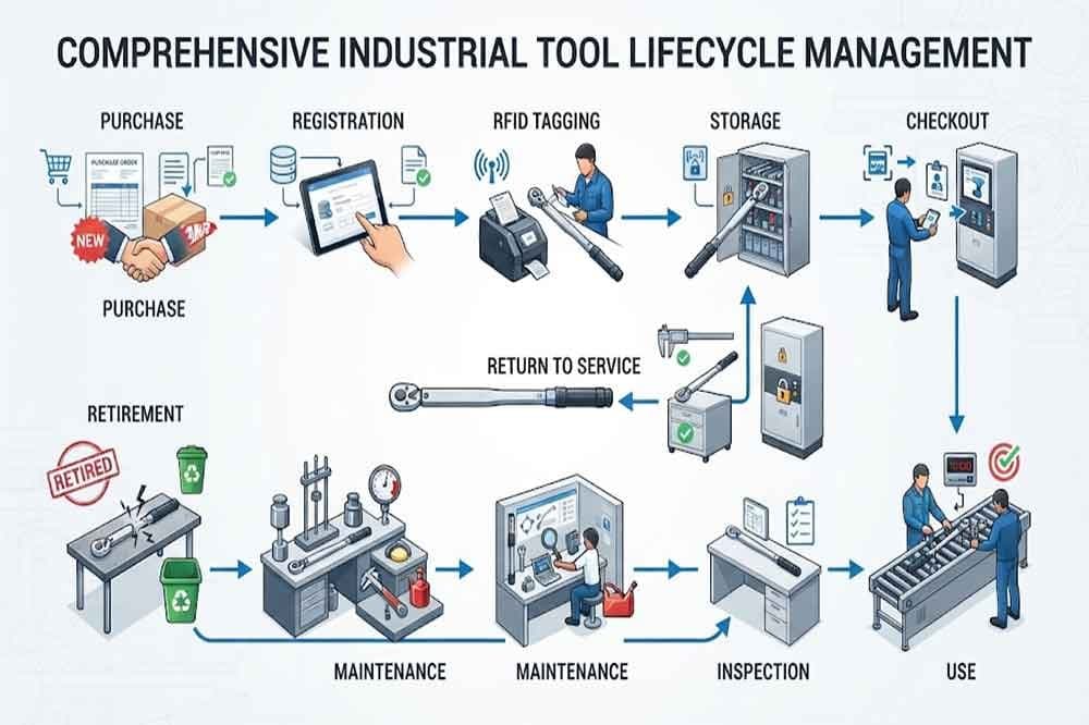
Photo shared by cykeo6688: RFID tool cabinet is designed to automate tool storage, tracking, checkout, return, and inventory. B
CY
cykeo6688@cykeo6688· September 24 at 9:00 AM

RFID Tool Control System for Workshops and Factories

A workshop can have a clear tool storage area and still struggle to control its equipment. Tools move between technicians, production lines, maintenance rooms, vehicles, and temporary work areas. Some are borrowed for a few minutes, while others remain outside storage for several days. When these movements are not recorded, managers may lose track of tool ownership, availability, and condition. This becomes more serious when tools are expensive, calibrated, safety-critical, or shared by multiple teams. An RFID tool control system helps organize this process by connecting physical tools with digital records, user permissions, storage locations, and usage history. Instead of relying entirely on manual checks, companies can use RFID technology to identify tools and monitor important control points automatically. What Is an RFID Tool Control System?​ An RFID tool control system is a combination of hardware and software used to manage tool access, movement, storage, and accountability. A typical system may include: RFID tags attached to tools UHF RFID readers RFID antennas RFID tool cabinets or carts User authentication devices Tool management software Inventory and maintenance records ERP or enterprise software integration Each tool receives a unique RFID identity. When the tool enters a reading zone, the system can identify it and update its status. The system may also connect the tool with a user, department, work order, or maintenance task. This creates a more complete record than simply counting tools in storage. Why Workshops Need Better Tool Control​ Tool control becomes difficult when equipment is shared and frequently moved. A factory maintenance team may use the same torque wrench across several production lines. An aviation department may need to control calibrated tools carefully. A repair workshop may send tool kits to different service locations. Without a clear control process, several problems can appear: Tools are returned to the wrong location Employees cannot find required equipment Missing tools are discovered too late Expired or damaged tools remain in circulation Manual records become inconsistent Managers cannot identify the last responsible user An RFID system does not replace every management rule. It helps make those rules easier to apply and monitor. How Does RFID Tool Control Work?​ RFID tool control workflow from user authentication to tool return 1. Assign a Digital Identity​ Each tool receives an RFID tag linked to a record in the management system. The record may include: Tool number Tool name Tool category Storage location Assigned department Calibration status Maintenance status Authorized users For metal tools, suitable on-metal RFID tags may be required. 2. Define Access Rules​ Not every employee needs access to every tool. The system can apply different access rules based on user role, department, training, or authorization level. For example, standard hand tools may be available to all technicians, while specialized measuring equipment may require approval. 3. Identify Tool Movement​ When a user removes or returns a tool through an RFID-enabled cabinet, cart, or reading zone, the reader detects the tag. The software can then update the tool status and connect the movement with the user. Possible statuses include: Available → Checked Out → In Use → Returned → Available Additional statuses may include: Under Maintenance → Calibration Required → Restricted → Missing 4. Monitor Exceptions​ A tool control system should also identify unusual situations. Examples include: A tool is overdue A restricted tool is accessed A tool is returned to the wrong location A tool is missing from expected inventory A calibrated tool is overdue for inspection A tool remains checked out after a work order is completed These exceptions allow managers to focus on problems instead of checking every tool manually. RFID Tool Control and User Accountability​ One of the main benefits of RFID tool control is the connection between a tool and its user. When employees authenticate before accessing tools, the system can record: Who accessed the tool Which tool was taken When it was taken Where it was stored When it was returned Whether the tool was overdue This creates a clearer responsibility chain. For example: User: Technician B Tool: Torque Wrench 024 Checkout Time: 09:15 Return Time: 13:40 Status: Returned These records can help managers investigate missing tools and understand usage patterns. However, the data should be treated as a record of system activity. It may not explain every event that happens after a tool leaves the reading area. RFID tool access control for authorized industrial users Controlling High-Value and Restricted Tools​ Some tools require stricter control than others. A basic screwdriver may only need inventory tracking. A calibrated torque wrench, specialized aviation tool, or high-value testing instrument may require additional controls. An RFID tool control system can support different management levels. Standard Tools​ Basic RFID identification General checkout records Routine inventory checks High-Value Tools​ User authentication Detailed movement history Restricted access Overdue notifications Calibrated Tools​ Calibration status Inspection reminders Maintenance records Restricted use after expiration Safety-Critical Tools​ Authorized-user access Mandatory return checks Work-order association Exception alerts This flexible structure helps companies apply stronger controls where they are actually needed. RFID control system for high-value and calibrated tools RFID Tool Cabinets and Tool Carts​ Different workplaces need different storage and control methods. An RFID tool cabinet is suitable for centralized storage. It can combine secure access, automatic tool identification, inventory checking, and user management. An RFID tool cart is more suitable when technicians need to move a complete tool set between work areas. A fixed RFID reading zone may work well at the entrance of a tool room or maintenance area. Handheld RFID readers can support mobile inventory checks and investigations. The right choice depends on how tools move through the workplace. A centralized tool room may benefit from a smart cabinet, while a mobile maintenance team may need an RFID cart or handheld device. RFID Tool Control for Maintenance Work Orders​ Tool control can become more useful when connected to maintenance tasks. For example, a technician may receive a work order requiring several specific tools. The system can record which tools were issued for that task and verify whether they were returned after the work was completed. This can help organizations: Prepare tool kits Associate tools with work orders Check tool returns Identify missing equipment Review tool usage history Support maintenance documentation The exact functions depend on the software and integration design, but the principle is straightforward: connect tool activity with the work being performed.

Photo shared by cykeo6688: A workshop can have a clear tool storage area and still struggle to control its equipment.

Tools
CY
cykeo6688@cykeo6688· September 23 at 9:43 AM

Long Range RFID Scanner for E-commerce Fulfillment Centers

E-commerce fulfillment centers handle a large number of orders, totes, cartons, picking batches, returns, and outbound shipments every day. A small tracking error can cause a missed order, incorrect parcel, delayed dispatch, or unnecessary manual checking. Barcode systems remain useful, but they normally require a clear view of the label and a scanning action at each checkpoint. A long range RFID scanner can identify tagged objects without requiring every tag to be directly visible. When installed at the right locations, it helps fulfillment operators monitor order movement, reusable containers, picking batches, packing activities, and outbound handovers. The goal is not to replace every barcode process. Instead, RFID can reduce repetitive scanning work and provide automatic visibility at important movement points. Why E-commerce Fulfillment Centers Need Better Tracking A typical fulfillment center includes several connected stages: Receiving inventory Putaway and storage Order release Picking Consolidation Packing Sorting Dispatch Returns processing Each stage may involve different workers, containers, conveyors, carts, and software systems. When tracking depends only on manual confirmation, the system may show that an order was picked even though the tote is still waiting in a staging area. Common operational problems include: Totes being sent to the wrong picking zone Order batches becoming mixed during consolidation Cartons reaching the wrong packing station Reusable containers leaving the facility without being recorded Parcels missing an outbound checkpoint Returned goods entering the wrong processing area Manual scans slowing down high-volume workflows Inventory and fulfillment records becoming inconsistent A long range RFID scanner can create automatic reading points at doors, conveyor transitions, staging lanes, packing areas, and dispatch gates. These reading points help connect physical movement with the fulfillment management system. How RFID Works in E-commerce Fulfillment A typical RFID fulfillment solution includes four main elements: RFID tags attached to totes, cartons, pallets, carts, or order containers Fixed or handheld RFID readers UHF RFID antennas Warehouse or fulfillment software The RFID reader sends radio signals through the antenna. When a compatible tag enters the reading zone, it responds with its stored identification data. The software then associates the tag ID with an order, tote, batch, location, or shipment record. RFID Tote Tracking in Fulfillment Operations For example, a tote may carry an RFID tag linked to: Tote ID Order batch number Picking wave Assigned zone Current process Destination packing station Dispatch status The tag itself does not need to store the complete order. In many systems, it only provides a unique ID, while the fulfillment software holds the detailed business information. This approach allows the same physical container to be tracked through multiple stages without printing a new label at every checkpoint. What Can a Long Range RFID Scanner Track? The most practical RFID targets in a fulfillment center are objects that move repeatedly or pass through controlled checkpoints. Reusable Totes and Bins Reusable totes are often shared between receiving, storage, picking, packing, and returns. Without automatic tracking, they can accumulate in the wrong area or disappear into another process. RFID can help record: Tote entry and exit Tote assignment to an order batch Tote movement between zones Empty tote returns Tote cleaning or inspection status Tote utilization frequency This is particularly useful when a fulfillment center owns thousands of reusable containers. Order Batches and Picking Carts Many facilities release orders in waves. A picking cart or batch container may include several orders that must remain separated until consolidation. An RFID tag can identify the cart, batch, or container as it moves between: Picking zones Consolidation stations Quality-check areas Packing stations Sortation lanes The reader does not need to identify every individual item to provide value. Tracking the container or batch can already improve process visibility. Cartons and Shipping Containers RFID can be used to identify cartons before they are sealed, after they are sealed, or when they pass through an outbound gate. The system can compare the carton ID with the expected order record and generate an alert when: A carton reaches the wrong lane A carton is missing from the expected batch A carton passes a checkpoint too early A carton is scanned more than once A carton is sent to the wrong carrier area Item-level RFID may be suitable for selected product categories, but carton-level tracking is often easier to implement as a first project. RFID for Receiving and Putaway At receiving, workers may unload goods from suppliers and move them to temporary staging areas. Barcode scanning can confirm individual cartons, but the process becomes slower when many containers pass through the same entrance. A long range RFID scanner installed at a receiving gate can automatically record tagged pallets, totes, or cartons entering the facility. The receiving system can compare the detected IDs with the expected delivery information. This helps identify: Unexpected containers Missing containers Duplicate records Incorrect receiving zones Unscheduled movements After receiving, RFID can also support putaway confirmation. When a tagged tote or pallet passes through a designated area, the system can record the movement and update the container location. The reading zone must be carefully designed. A reader positioned near several storage aisles may detect tags from neighboring locations, so directional antennas, shielding, power adjustment, and software filtering may be necessary. RFID for Order Picking Order picking is one of the most important stages in e-commerce fulfillment. A picking error can affect customer satisfaction, shipping costs, and return rates. RFID can support picking in several ways. Tracking Picking Carts A cart may be assigned to a picking wave or a group of orders. RFID checkpoints can confirm when the cart leaves the staging area, enters a picking zone, or returns to consolidation. This creates a movement history without requiring workers to scan the cart manually at every transition. Confirming Order Containers An RFID tag on a tote can be linked to a specific order batch. When the tote reaches a consolidation or packing station, the system can check whether it is expected there. If the wrong tote arrives, the software can show an exception message before the order proceeds further. Supporting Zone-Based Picking In large facilities, orders may be divided between different picking zones. RFID can help monitor the movement of containers between these zones. The system may record: Container ID Picking zone Time of arrival Time of departure Assigned order group Next destination RFID does not automatically guarantee picking accuracy. The fulfillment software still needs correct order logic, and workers may need barcode or visual confirmation for individual products. RFID works best as an additional layer of process control. RFID Order Picking and Batch Tracking RFID for Consolidation and Packing Stations After picking, order items may be brought together before packing. This stage can create confusion when many totes or order batches arrive at the same time. A long range RFID scanner near the consolidation area can identify incoming containers and match them with the expected order group. At the packing station, RFID can help confirm: The correct tote has arrived The order is ready for packing The carton is assigned to the correct shipment The carton has passed a required inspection The order is moving to the correct outbound lane For high-volume operations, the reader may be connected to a local display or workstation. The software can show the expected order information as the tagged container enters the reading zone. This reduces the need for workers to stop and search for a label, although visual confirmation may still be required for certain products or compliance processes. RFID for Parcel Sorting and Outbound Shipping Outbound sorting involves moving packed orders toward carrier lanes, dispatch doors, or regional distribution areas. A long range RFID scanner can be installed at a conveyor transition, sortation lane, or shipping gate. The system can compare the detected carton or container ID with the expected destination. Possible actions include: Confirming the carton entered the correct lane Triggering a conveyor diversion Recording the time of outbound movement Updating shipment status Alerting staff when a carton enters the wrong zone Confirming that a dispatch batch has left the facility The reader’s actual performance depends on tag placement, carton material, conveyor speed, antenna layout, and the distance between the tag and antenna. Testing is necessary before selecting the final reader power and antenna arrangement. RFID for Returns Management Returns often follow a different route from normal outbound orders. Returned goods may move through inspection, grading, repacking, restocking, repair, or disposal. RFID can help identify reusable return containers and track their movement through the returns area. A tagged container can be associated with: Return authorization number Customer return batch Inspection status Product condition Restocking decision Repair or disposal destination For individual product tracking, RFID tags may be applied to selected product categories or internal handling units. However, not every product requires an RFID tag. The project should focus on products and containers where automatic identification creates measurable operational value. Challenges When Using RFID in Fulfillment Centers RFID can improve movement visibility, but it is not a plug-and-play replacement for every barcode scanner. Tag Placement Tags placed close to metal surfaces, liquids, dense products, or electronic components may have reduced reading performance. The best tag location should be tested with real packaging and actual products. Unwanted Reads A long range RFID scanner may detect tags outside the intended area if the reading zone is too open. This can create false movement records. Possible controls include: Directional antennas Lower reader power Physical shielding Reader trigger sensors Software time filters Zone-based reader logic Multiple-read confirmation Multiple Containers Passing Together When several totes or cartons pass through a gate at the same time, the system must determine whether they belong to the same batch or different orders. The software should use event timing, reader location, expected workflow, and container status to avoid assigning every detected tag to the same transaction. Packaging Materials Cardboard is generally RFID-friendly, but some products and packaging may contain metalized films, liquids, dense materials, or conductive components. These materials can affect reading distance and consistency. A practical test should use the actual tote, carton, tag, and product combination instead of relying only on laboratory specifications. Creating Controlled RFID Reading Zones The most reliable fulfillment RFID systems do not simply install a powerful reader and expect it to identify everything nearby. Each reading point should have a clear business purpose. Examples include: Receiving gate: record incoming containers Picking exit: confirm cart movement Consolidation station: identify order batches Packing entrance: confirm container assignment Sortation lane: verify destination Dispatch gate: record outbound movement Returns entrance: register returned containers For each zone, define: Which objects should be detected Which objects should not be detected The expected movement direction The acceptable reading distance The software event triggered by a read The response when an unexpected tag is detected This approach is more effective than trying to maximize reading distance everywhere. Integrating RFID with Fulfillment Software A long range RFID scanner becomes useful when its data is connected to the fulfillment system. Depending on the project, integration may involve: Warehouse Management System Order Management System Enterprise Resource Planning software Transportation Management System Conveyor control system Inventory platform Custom fulfillment software Common integration methods include Ethernet, TCP/IP, serial communication, digital inputs and outputs, REST APIs, or an SDK supplied by the reader manufacturer. RFID Integration with Fulfillment Software A typical event may look like this: Reader detects tote ID. Middleware checks the reader location. Software identifies the tote’s current order or batch. The system compares the expected destination. The event is recorded. An alert or control action is triggered when necessary. The software should also prevent duplicate events. A tag remaining in the reading zone for several seconds should not create multiple receiving or shipping transactions. Practical Example: Tracking Order Totes Consider a fulfillment center that uses reusable totes for multi-order picking. Each tote receives an RFID tag linked to its container ID. When a tote is assigned to a picking wave, the software connects the tote ID with the relevant order batch. As the tote moves through the facility: A reader records its exit from the staging area. Another reader confirms arrival at the consolidation zone. The system checks whether the tote belongs to the expected batch. A packing station reader confirms the tote’s destination. After packing, the empty tote is detected at the return point. The software updates the tote as available for the next cycle. This workflow does not require RFID tags on every individual product. Tracking the reusable container may already provide better visibility and reduce manual scanning. How to Test a Long Range RFID Scanner in a Fulfillment Center Before full deployment, conduct a site test using real operating conditions. The test should include: Actual totes and cartons Different tag positions Empty and full containers Different conveyor speeds Multiple containers passing together Nearby metal structures Adjacent reading zones Normal worker movement Real software event timing Measure more than maximum reading distance. Important indicators include: Read consistency False-read rate Missed-read rate Reading-zone width Detection speed Performance with multiple tags Integration response time Stability during peak operation A reader that performs well in an open test may behave differently when installed beside conveyors, racks, motors, metal frames, or other RFID equipment. Procurement Checklist When selecting a long range RFID scanner for an e-commerce fulfillment project, consider: Supported UHF frequency range EPC Gen2 or ISO18000-6C compatibility Required reading distance Antenna quantity and layout Fixed or handheld installation Ethernet or serial communication API or SDK availability Digital input and output support Reader power adjustment Multi-tag reading performance Trigger and sensor integration Protection rating for the installation area Software compatibility Tag testing and customization support OEM or system integration requirements The final selection should be based on the complete reading zone, not only the reader’s advertised maximum distance. Final Takeaway A long range RFID scanner can help e-commerce fulfillment centers track reusable totes, order batches, picking carts, cartons, returns, and outbound movements with less manual scanning. The strongest applications usually involve controlled movement points where the system needs to know that a tagged object has entered, left, or reached a specific area. RFID can improve fulfillment visibility, but successful deployment depends on tag selection, antenna placement, reading-zone control, software integration, and testing with real packaging. For many fulfillment centers, starting with tote tracking, batch movement, or outbound carton verification provides a practical way to measure value before expanding into more complex item-level RFID tracking. For facilities that need to connect fulfillment operations with stock visibility, RFID warehouse inventory tracking can provide a broader view of container and inventory movement. For apparel fulfillment, RFID for clothing inventory can connect store-level product visibility with warehouse picking and order preparation. Explore long range RFID scanner solutions for fixed reading points, multi-antenna installations, warehouse gates, conveyors, and industrial tracking applications.

Photo shared by cykeo6688: E-commerce fulfillment centers handle a large number of orders, totes, cartons, picking batches, ret
CY
cykeo6688@cykeo6688· September 22 at 8:09 AM

How to Set RFID Card

Connect RFID Card Writer Hardware​ After selecting the correct card, connect the RFID reader writer to the computer system. For professional card setup stations, the hardware usually includes: RFID reader writer device USB communication connection RFID programming software Card management database Cykeo desktop RFID writers are designed for controlled card programming environments. The device uses a near-field antenna structure to limit unnecessary reading and writing areas. This design is especially useful when operators need to configure one RFID card at a time without affecting nearby cards. Technical features include: Impinj R500 RFID platform Maximum output power up to 33 dBm Reading distance controlled within approximately 30 cm Writing distance controlled within approximately 10 cm Mini USB communication C# and Java development resources 3. Write Data to RFID Card​ The actual setup process depends on the RFID card memory structure and application requirements. Typical writable information includes: Unique identification numbers Product information Asset management codes User identification data Application-specific parameters During deployment, experienced engineers usually avoid writing unnecessary information into RFID memory. Keeping data structure simple improves system stability and makes future maintenance easier. https://www.cykeorfid.com/rfid-product/rfid-readers/

Photo shared by cykeo6688: Connect RFID Card Writer Hardware​
After selecting the correct card, connect the RFID reader writer
CY
cykeo6688@cykeo6688· September 21 at 7:33 AM

How to Scan RFID Tags

how to scan rfid tags: Quick Answer​ How to scan rfid tags? RFID tags are scanned by using a compatible RFID reader that sends radio frequency signals to activate the tag and capture stored information. The reader, antenna, frequency, and software must work together for accurate identification and reliable data collection. Understanding How to Scan RFID Tags in Real Applications​ RFID tag scanning is not simply placing a reader close to a tag and receiving data. In actual deployments, successful scanning depends on several technical factors, including RFID frequency, tag material, reader performance, antenna configuration, and environmental conditions. During years of working with RFID deployment projects, Cykeo engineers have tested RFID systems in warehouses, manufacturing facilities, retail stores, and asset management environments. One common field issue is not the RFID tag itself, but the mismatch between the tag type and the selected reader. For example, a warehouse using UHF RFID tags for pallet tracking requires a reader designed for long-range identification, while a desktop workstation for card or label registration needs controlled near-field reading. The same RFID technology behaves differently depending on the application. According to GS1, RFID systems are commonly built around three core elements: RFID tags, readers, and software platforms. The reader captures tag information and transfers the data into business systems for tracking and decision-making. From practical experience, reliable RFID scanning requires attention to details that are often overlooked: Matching the RFID reader frequency with the RFID tag frequency Selecting suitable antennas for the reading environment Adjusting reader power output according to application requirements Filtering unwanted tag reads in dense environments Integrating RFID data with existing software systems How RFID Tag Scanning Works Step by Step​ When scanning RFID tags, the reader and tag communicate through electromagnetic waves. Passive RFID tags do not contain their own power source. Instead, they receive energy from the reader signal and return stored information. The basic scanning process includes: Process Technical Function RFID reader activation Sends RF energy through antenna Tag response RFID chip transmits stored identification data Signal processing Reader filters and decodes received information Data transmission Information moves to software or database Application action System updates inventory, access, or tracking records 1. Select the Correct RFID Reader​ The first step in scanning RFID tags is choosing a reader that matches the tag technology. Common RFID frequencies include: RFID Frequency Typical Application LF 125–134 kHz Animal identification, simple access applications HF 13.56 MHz RFID cards, library systems, NFC-related applications UHF 860–960 MHz Warehouse inventory, logistics, asset tracking For enterprise applications, UHF RFID is widely adopted because it supports fast identification of multiple tags over longer distances. Auburn University’s RFID Lab has conducted extensive RFID research in retail environments, including studies showing RFID can significantly improve inventory accuracy when properly implemented. Their research has been widely referenced in retail RFID adoption. 2. Position the RFID Tag Within the Reader Range​ The scanning distance depends on: Reader output power Antenna gain Tag antenna design Surrounding materials Installation environment In a controlled workstation, a short reading distance may be preferred because operators need to scan one specific tag. In a warehouse, however, fixed RFID readers with external antennas may be installed at gateways, shelves, or production lines to automatically capture multiple tagged items. Cykeo RFID readers support professional deployment scenarios with features such as: ISO18000-6C / EPC C1G2 compatibility Multi-tag identification capability Adjustable output power Anti-collision algorithms SDK/API integration support Warehouse worker scanning RFID tags using UHF RFID reader system UHF RFID scanning enables automatic identification of tagged products in warehouse operations. Common Problems When Scanning RFID Tags​ In real projects, RFID scanning problems usually come from environmental conditions rather than the basic RFID principle. Common issues include: Incorrect RFID Frequency​ A UHF reader cannot properly scan an HF RFID card because the operating frequencies are different. Metal and Liquid Interference​ Metal surfaces and liquids can affect RF performance. Special RFID tags or installation adjustments may be required. Too Many Tags in the Reading Area​ Dense tag environments require anti-collision technology and filtering algorithms to prevent missed or unnecessary reads. Poor Reader Installation​ A technically strong RFID reader can still perform poorly if antennas are positioned incorrectly. Cykeo Experience: Improving RFID Tag Scanning Reliability​ In RFID deployment projects, engineers often focus on reading distance first. However, stable identification is usually more valuable than maximum range. A warehouse does not always need a reader that detects every tag 15 meters away. It needs predictable reads at the correct location. Cykeo RFID solutions are designed around this practical requirement. Key advantages include: Professional UHF RFID hardware development experience High-speed multi-tag recognition Adjustable RF output control Industrial communication interfaces DEMO software and SDK support Flexible integration with customer systems For example, Cykeo fixed RFID readers can be deployed at warehouse entrances, production stations, and inventory checkpoints to automatically capture RFID tag information without manual scanning. How to Scan RFID Tags in Industrial Environments​ In small applications, scanning an RFID tag may only require a desktop reader and simple software. Industrial environments are different. A warehouse, factory, or logistics center usually contains thousands of tags, moving objects, metal structures, and multiple reading points.

Photo shared by cykeo6688: how to scan rfid tags: Quick Answer​
How to scan rfid tags? RFID tags are scanned by using a compat
CY
cykeo6688@cykeo6688· September 20 at 6:01 AM

how to rfid tags work: A Practical Guide to RFID Tag Technology

RFID tags work by exchanging wireless signals with RFID readers through radio frequency communication. The reader sends energy to activate the tag, and the embedded chip returns stored identification data. This process enables automatic tracking, inventory control, and asset management without direct scanning or physical contact. Understanding the Basic Principle Behind RFID Tags how to rfid tags work starts with understanding the relationship between the RFID tag and the reader. An RFID tag is not simply a sticker with information printed on it. Inside the tag is a small electronic circuit containing a chip and antenna that allows wireless communication. In practical deployments, I have tested RFID systems in warehouse inventory, manufacturing tracking, retail management, and equipment identification environments. One thing becomes clear during installation: the tag itself is only one part of the system. Reader configuration, antenna position, surrounding materials, and software processing often determine the final performance. A common mistake during RFID projects is focusing only on tag selection while ignoring the reading environment. A tag that performs well on cardboard packaging may behave differently when attached to metal equipment or liquid containers. Field testing before large-scale deployment remains one of the most important steps. According to GS1, RFID technology supports automatic identification and data capture by using radio waves to exchange information between tags and readers. EPC-based RFID systems are widely used for product identification and supply chain visibility. How RFID Tags Communicate With RFID Readers The communication process between an RFID tag and reader happens through electromagnetic waves. Unlike barcode systems, RFID does not require a direct visual connection between the reader and the tagged object. The basic workflow includes: Step Process 1 RFID reader sends radio frequency signals through an antenna 2 RFID tag receives energy from the reader signal 3 RFID chip processes stored identification information 4 Tag sends data back to the reader 5 Software system collects and manages the information Passive RFID tags, which are widely used in logistics and retail, do not contain their own battery. They receive power from the reader signal and respond by reflecting a modified radio frequency signal. Active RFID tags work differently because they contain an internal power source. They can provide longer communication distances but are usually used for specialized tracking scenarios. How RFID Tags Store Information Inside an RFID tag, the microchip stores digital information that identifies an item. The amount and type of stored data depend on the tag standard and application requirements. A typical UHF RFID tag structure includes several memory areas: Memory Area Purpose EPC Memory Stores unique identification numbers TID Memory Stores chip-related information User Memory Stores additional application data Reserved Memory Handles security functions Most enterprise RFID systems do not store complete product records directly on the tag. Instead, the RFID number acts as a digital key connected to a database. For example, in a warehouse environment, a pallet tag may only contain a unique EPC number. When the reader captures this number, the warehouse management system retrieves product details, location information, receiving status, or shipping records. This design allows companies to update inventory information without rewriting every physical RFID tag. RFID Frequency Determines How Tags Work RFID technology operates across different frequency ranges. The frequency affects reading distance, application environment, and system design. Frequency Range Typical Applications LF (125–134 kHz) Short distance Animal tracking, access systems HF (13.56 MHz) Medium distance Smart cards, NFC, libraries UHF (860–960 MHz) Longer distance Warehouses, retail, logistics For industrial applications, UHF RFID is commonly selected because it supports fast identification of multiple items. The Auburn University RFID Lab has conducted RFID research focused on inventory accuracy and retail applications. One widely referenced study involving retail stores showed RFID could significantly improve inventory record accuracy when properly implemented. The research highlighted that RFID performance depends on complete system deployment rather than simply attaching tags to products. RFID tag transmitting data to a fixed RFID reader in a warehouse environment RFID readers capture wireless tag information to improve inventory visibility and automated identification. What Happens Inside an RFID System During Real Deployment? When an RFID project moves from testing into daily operation, several technical details become important. Key factors include: Reader output power adjustment Antenna installation angle Tag placement direction Environmental interference Data filtering configuration Software integration During warehouse deployments, engineers often discover unexpected issues after installation. Metal racks may reflect radio signals. Closely packed products may create multiple tag reads. A reader may capture hundreds of responses per second but still require software filtering to provide accurate business data. This is where industrial RFID systems differ from simple demonstrations. A successful solution must combine reliable hardware, optimized communication settings, and practical application software. Cykeo develops RFID hardware solutions designed for industrial environments, including UHF fixed rfid readers, RFID reader modules, desktop RFID writers, and integrated identification systems. These solutions support functions such as multi-tag reading, adjustable power control, filtering algorithms, and SDK/API integration for customized applications. How RFID Tags Work in Real Business Applications Understanding how to rfid tags work becomes more valuable when looking at real deployment environments. RFID technology is not only used for identifying products; it creates a continuous connection between physical objects and digital management systems. In warehouse operations, RFID tags can be attached to cartons, pallets, tools, or individual products. When items pass through an RFID reading zone, the system automatically captures identification information and updates inventory records.

Photo shared by cykeo6688: RFID tags work by exchanging wireless signals with RFID readers through radio frequency communicatio
CY
cykeo6688@cykeo6688· September 18 at 9:24 AM

Long Range RFID Scanner for Power Plants: How to Track Equipment and Maintenance Assets

How Does RFID Tracking Work in a Power Plant?​ A typical power plant RFID workflow looks like this: RFID tag → antenna → long range RFID scanner → EPC identification → software record → maintenance or inventory event For example, a tagged maintenance tool leaves the central warehouse. A reader at the warehouse exit detects the tag and sends its EPC to the asset management system. The software can then update the tool status from “stored” to “issued” or “in transit.” When the tool arrives at a workshop or substation, another reader can record the next checkpoint. The reader identifies the tag. The software decides what the detection means. That distinction matters because the same RFID event may represent different actions depending on the location, direction, time, work order, and asset status. Tracking Power Plant Equipment​ Power plants contain many valuable assets that move between storage, maintenance, operation, and inspection areas. Potential RFID-tracked assets include: Maintenance tools Testing instruments Portable generators Pumps and motors Electrical cabinets Switchgear components Transformers and spare parts Cable drums and reels Toolboxes and equipment cases Safety equipment Inspection devices Reusable transport containers Maintenance carts Spare parts bins Some equipment remains in a fixed location for years. Other items move frequently between workshops, warehouses, substations, and field service areas. For fixed assets, RFID can support periodic inspection and inventory confirmation. For mobile assets, it can provide a record of movement between defined checkpoints. A long range RFID scanner is particularly useful when workers need to identify several tagged items without scanning each barcode individually. RFID tracking power plant equipment and maintenance assets. RFID for Maintenance Tools and Equipment​ Maintenance teams often lose time searching for tools, testing instruments, and portable equipment. A tool may be: In the central warehouse Assigned to a maintenance team Inside a workshop At a substation In a service vehicle Waiting for inspection Returned but not yet recorded RFID can improve visibility by connecting the asset ID with a location, user, work order, or maintenance status. A fixed reader at a workshop entrance may detect tools entering or leaving the area. A handheld RFID reader can then support shelf-level checks or locate a missing item nearby. For many power plants, a combination of fixed and handheld readers is more practical than using only one type of equipment. Metal Equipment Requires Careful Tag Selection​ Power plant environments contain large amounts of metal. Transformers, electrical cabinets, generators, motors, cable reels, toolboxes, and industrial containers can affect RFID performance. A standard RFID label may not work properly when attached directly to a metal surface. Depending on the application, an on-metal RFID tag or rugged industrial tag may be more suitable. Tag selection should consider: Metal or non-metal mounting surface Required reading distance Tag orientation Outdoor or indoor installation Temperature changes Oil, dust, moisture, and chemicals Mechanical impact UV exposure Cleaning procedures Expected service life The best tag is not necessarily the one with the longest advertised reading distance. It is the one that remains readable on the actual asset under real operating conditions. On-metal RFID tags attached to power plant equipment. Harsh Conditions at Energy Facilities​ Power plants and substations may expose RFID equipment and tags to conditions that are more demanding than a normal warehouse. Possible factors include: Dust and dirt Moisture and rain High or low temperatures Vibration Electromagnetic equipment Metal structures Outdoor sunlight Oil and industrial chemicals Heavy machinery Restricted installation space The RFID reader, antenna, cable, connector, and tag should be selected as a complete system. If the installation is near high-voltage equipment or in a hazardous area, the project team must also verify the required electrical safety, environmental, and site certifications. A standard RFID reader should not automatically be assumed suitable for every power plant area. Why Antenna Position Matters​ A long range RFID scanner does not simply read every tag within a large circle. Its actual reading area depends on the antenna pattern, mounting position, reader power, tag performance, and surrounding environment. For example, a reader installed at a workshop entrance may detect assets passing through the doorway. However, if the antenna points toward an adjacent storage area, it may also read tags that are not supposed to be included in the event. A controlled reading zone can be created by adjusting: Antenna direction Antenna height Antenna angle Reader output power Distance from the asset Physical barriers Lane or doorway layout Trigger sensors Software filtering In a power plant, the goal is usually not to maximize the reading distance. The goal is to identify the correct equipment at the correct checkpoint. Tracking Equipment Between Warehouses and Substations​ Energy companies often move tools, spare parts, and equipment between several locations: Central warehouse → maintenance workshop → substation → field service area → return warehouse RFID can record these movements when readers are installed at suitable points. For example, a tagged transformer component may be detected when it leaves the warehouse, arrives at a service workshop, and returns after maintenance. The software can compare the expected movement with the actual detection history. This can help answer practical questions: Where was the equipment last detected? Has the item returned from maintenance? Which tools are currently assigned to a service team? Which spare parts left the warehouse? Which assets remain at a remote substation? Was the correct equipment delivered to the work area? The system still depends on checkpoint placement. If an asset moves through an area without an RFID reader, the software may not receive a new location event. Can RFID Read Multiple Power Plant Assets?​ UHF RFID technology can identify multiple tags within a reading zone. This makes it useful for tool carts, equipment cases, spare parts bins, and groups of maintenance assets. However, actual performance depends on: Number of tags Tag spacing Tag orientation Metal surfaces Reading distance Antenna position Reader power Asset movement speed Nearby electrical equipment Software filtering Whether tags are stacked or enclosed A cart carrying twenty tagged tool cases may behave differently from twenty loose tags placed on a table. For this reason, testing should use the actual equipment, tag type, cart design, and movement process rather than relying only on a laboratory demonstration. RFID and Power Plant Asset Management Software​ The RFID reader produces tag identification data. The software connects that data to operational meaning. Depending on the project, the system may integrate with: Maintenance management software Enterprise asset management systems Warehouse management systems ERP platforms Inventory databases Work order systems Substation management platforms Access control systems Digital inspection platforms Common communication methods may include Ethernet, TCP/IP, serial communication, digital I/O, API, SDK, HTTP, or MQTT, depending on the reader model and software architecture. For example, the software may apply rules such as: A tool detected at the workshop entrance is marked as received. A spare part detected at the warehouse gate is marked as dispatched. An asset detected at a maintenance area is linked to an open work order. A tool detected twice within a short period is treated as one movement event. A tag detected in an unexpected area creates an alert for review. The reader supplies the detection. The application supplies the workflow.

Photo shared by cykeo6688: How Does RFID Tracking Work in a Power Plant?​
A typical power plant RFID workflow looks like this:
CY
cykeo6688@cykeo6688· September 17 at 8:56 AM

Long Range RFID Scanner for Manufacturing: How to Track Products on Production Lines

Long range RFID scanner can automatically identify tagged products, containers, tools, and work-in-process items as they move through different production stations. The real benefit comes from combining the RFID reader with properly positioned antennas, RFID tags, sensors, PLCs, and manufacturing software. Manufacturing plants usually have a simple problem that becomes surprisingly complicated at scale: where is this product right now? A component may pass through machining, assembly, inspection, testing, packaging, and storage before it becomes a finished product. If every movement depends on manual barcode scanning, production data can quickly become incomplete. This is where RFID manufacturing systems become useful. A long range RFID scanner can identify products without requiring an operator to stop and scan each item individually. When the reader, antenna, RFID tag, and production software are configured correctly, the system can automatically record that a product has entered or left a particular production station. But there is an important point here: RFID does not automatically understand the manufacturing process. The reader detects the RFID tag. The software decides what that detection means. That distinction matters when designing a production line. RFID reader tracking products moving through a manufacturing production line What Does RFID Do on Manufacturing Line?​ The basic process is quite straightforward: RFID tag → reading zone → RFID reader → EPC data → production software → manufacturing event For example, imagine a metal component moving from Station 2 to Station 3. The component has RFID tag with a unique EPC number. When it enters the RFID reading area, the long range RFID scanner detects the tag. The system can then associate that EPC with a product record: Product ID Work order Production station Processing status Timestamp Operator or machine Quality inspection status The next time the same tag appears at another station, the software updates the production history. This creates a digital trail for the work-in-process item. Why WIP Tracking Is a Strong RFID Application​ Work-in-process, or WIP, is one of the areas where RFID can make a noticeable difference. In a busy factory, unfinished products often sit in carts, bins, trays, racks, or temporary storage areas. A worker may know where something is physically, but the production system may not know. Barcode systems can work well, but they usually require the code to face the scanner. RFID doesn’t need the same line-of-sight operation. A worker can move a cart containing multiple tagged items through an RFID reading zone, and the reader may identify several tags during the same event. Of course, “may” is important. If the tags are stacked tightly together, mounted against metal, or surrounded by materials that absorb RF energy, the result can be very different from a clean laboratory test. I’ve seen production applications where the reader itself wasn’t the problem. The tag location was. Antenna Position Often Matters More Than Reader Power​ When a production line has reading problems, increasing reader power is usually the first idea people have. It isn’t always the best one. A manufacturing RFID system needs a controlled reading zone, not simply the largest possible reading distance. Suppose a product needs to be detected only when it reaches Station 4. If the reader can detect that product several meters before Station 4, the software may receive the event too early. That creates another problem: the RFID system may know the tag is nearby, but not exactly where the manufacturing process expects it to be. Antenna placement helps control this. Depending on the product and conveyor design, antennas can be installed: Beside the conveyor Above the production line Under the conveyor On both sides Around an RFID tunnel Near workstation entrances For some applications, two antennas facing the product from different directions provide much better reliability than one antenna operating at higher power. Tag Placement Is a Manufacturing Design Issue​ RFID tags should not simply be stuck onto the product wherever there is space. In manufacturing, the product may contain: Metal parts Motors Batteries Liquids Cables Electronic components Metal containers Plastic housings These materials can affect RFID performance. For metal products, an on-metal RFID tag may be necessary. For plastic products, a standard UHF RFID label might work perfectly well. For a production tray containing several components, the tag may need to be placed on the outside of the tray rather than between the products. This is why I would recommend testing the actual product before choosing the final RFID tag. A tag that works beautifully on a sample carton may perform poorly once the same tag is attached to a finished metal assembly. Production Speed Changes the Reading Requirement​ Production speed is another detail that is easy to overlook. Imagine a product moving slowly through an RFID reading zone. The reader has plenty of time to detect the tag. Now increase the conveyor speed. The product spends less time inside the effective reading area. If the tag orientation is poor or the reading zone is too small, missed reads may start appearing. This doesn’t mean every high-speed production line needs an expensive reader. It means the RFID system needs to be tested at the actual production speed. A useful test normally includes: Normal conveyor speed Maximum conveyor speed Different tag orientations Different product positions Minimum product spacing Multiple products passing together Repeated passes If the system works only when the conveyor is running slowly, it isn’t ready for production. RFID Can Work With PLCs and Sensors​ A production RFID reader usually works as part of a larger automation system. The RFID reader identifies the tag. A sensor can tell the system that a product has physically arrived. A PLC can control the machine. Production software can record the event. For example: Photoelectric sensor detects product → PLC triggers RFID reading → reader identifies EPC → software checks product record → production station starts This approach can make the RFID reading process much more controlled. Depending on the reader model, communication may include Ethernet, TCP/IP, serial communication, digital I/O, HTTP, MQTT, API, or SDK interfaces. The exact interface matters when an RFID system integrator needs to connect the reader to existing factory equipment. RFID work in process tracking between manufacturing stations What About Multiple Products at Once?​ Manufacturing environments rarely move products one at a time. A tray might contain ten components. A cart might carry thirty. Several tagged containers may pass through the same reading zone within a few seconds. UHF RFID is useful here because the reader can identify multiple tags in the same RF field. But the software still needs to determine what those reads mean. For example, if ten components are expected at Station 5 and only nine EPCs are detected, the system can flag a missing item. That is much more useful than simply displaying ten EPC numbers on a screen. The manufacturing application needs to turn RFID reads into meaningful production events.

Photo shared by cykeo6688: Long range RFID scanner can automatically identify tagged products, containers, tools, and work-in-p
CY
cykeo6688@cykeo6688· September 16 at 9:43 AM

Long Range RFID Scanner for Toll Roads: How RFID Automates Vehicle Identification

Toll roads need to identify vehicles quickly. When a vehicle approaches a toll point, the system may need to recognize the vehicle, check its account or authorization, record the passage, and then trigger the next step in the process. A long range RFID scanner can help with this by identifying an RFID tag attached to a vehicle without requiring the driver to stop and manually scan a card. The interesting part is that the RFID reader is only one piece of the system. The antenna, vehicle tag, lane layout, vehicle speed, sensors, barrier controller, and software all affect whether the system works reliably. How RFID Vehicle Identification Works on Toll Roads​ A basic RFID toll identification process looks like this: Vehicle tag → RFID antenna → RFID reader → identification data → toll software An RFID tag is attached to the vehicle or placed in a suitable position. As the vehicle approaches the toll checkpoint, the long range UHF RFID reader detects the tag through its antenna. The reader receives the tag ID and sends it to the toll management system. The software can then determine what should happen next. For example: Identify the vehicle Check the vehicle account Record the checkpoint Record the passage time Check access permissions Associate the vehicle with a transaction Trigger a barrier or traffic-control device The RFID reader provides the identification event. The software handles the business logic. Why Use RFID for Vehicle Identification?​ Traditional vehicle identification can rely on tickets, manual cards, QR codes, license plate recognition, or other technologies. RFID offers another approach. The vehicle does not necessarily need to stop and present a barcode to a scanner. A fixed RFID reader can detect the tag as the vehicle passes through a defined reading area. This can be useful when many vehicles need to pass through the same checkpoint. For example, a private road may have hundreds or thousands of registered vehicles using the same entrance every day. Instead of requiring each driver to interact with a terminal, RFID can make the identification process more automatic. Of course, RFID is not always the only technology required. Cameras, vehicle sensors, barriers, and other systems may still have important roles. Long Range Does Not Mean Unlimited Coverage​ There is a common misunderstanding with the term “long range RFID scanner.” Some buyers think a longer reading distance is always better. For a toll road application, that is not necessarily true. The system normally needs to know when the vehicle reaches a specific checkpoint. If the reader detects a vehicle too early, the software may record the event before the vehicle actually reaches the toll point. A very wide reading zone can also create problems when multiple lanes are close together. For this reason, antenna direction and reading-zone control are extremely important. A good RFID toll installation aims for a stable detection area rather than simply the maximum possible reading distance. Controlling the RFID Reading Zone​ The antenna creates much of the practical reading behavior. Depending on the road layout, an antenna may be installed beside the lane or positioned above the vehicle path. The installation needs to consider: Lane width Vehicle height Antenna angle Reading distance Tag location Reader output power Road direction Vehicle speed Adjacent lanes Metal structures Weather and environmental conditions The exact configuration depends on the application. A small private toll entrance may need a very different antenna arrangement from a multi-lane transportation checkpoint. This is one reason field testing matters before selecting the final hardware configuration. Controlled RFID reading zone for toll road vehicle identification RFID Tags on Vehicles​ Vehicle tags can be installed in different locations depending on the application. A windshield-mounted RFID tag may work well for some systems. Other applications may require a tag designed for mounting on or near metal surfaces. The tag’s orientation also matters. A vehicle does not always approach the antenna at exactly the same angle. Different vehicle models may also have different windshield angles, mounting heights, and structures around the tag. For a supplier or system integrator, testing several vehicle types can reveal problems that a single laboratory test will not show. A reader may detect a loose tag very easily, while the same tag performs differently after installation on a real vehicle.

Photo shared by cykeo6688: Toll roads need to identify vehicles quickly.

When a vehicle approaches a toll point, the system
CY
cykeo6688@cykeo6688· September 15 at 8:09 AM

how to program rfid reader

To program an RFID reader, configure communication parameters, set reader commands, adjust RF settings, connect the SDK or API, and test tag reading performance in the actual application environment. Proper programming ensures reliable identification, stable data transmission, and accurate RFID system operation. Programming an RFID reader is not simply sending a command to “start reading tags.” In a production RFID project, the reader becomes a communication bridge between physical objects and software systems. The configuration determines how tags are detected, how often data is reported, how duplicate reads are handled, and how the application interprets each RFID event. During RFID deployments, I have found that many integration problems are not caused by the reader hardware itself. They usually appear at the connection point between the reader settings and the business workflow. A warehouse reader may capture thousands of tag observations, but the inventory system only needs meaningful events. A tool-management reader may detect a tagged tool, but the software must know whether it represents borrowing, returning, or an unauthorized movement. That difference is where professional RFID programming begins. According to the GS1 RFID standards ecosystem, RFID systems involve multiple layers, including tag identification, reader communication, middleware processing, and event-level data exchange. Standards such as EPC Gen2 / ISO 18000-63 and EPCIS help create interoperability between RFID hardware and business applications. Understanding RFID reader programming before configuration RFID reader programming includes several technical layers A complete RFID reader setup usually involves: Programming Layer Purpose Common Configuration Communication layer Connect reader with software USB, RS-232, Ethernet, TCP/IP RF configuration Control wireless performance Output power, frequency, antenna ports Inventory command Control tag scanning Start, stop, continuous inventory Tag filtering Reduce unnecessary data EPC filtering, duplicate removal Data processing Convert reads into events Time stamps, reader location Application interface Connect business software SDK, API, middleware A common mistake is treating reader programming as a one-time setup task. In reality, RFID readers are usually tuned during commissioning. The correct output power for a warehouse doorway may be completely different from a desktop registration station. A reader mounted beside metal shelving may require different antenna settings than one installed in an open area. How to program a UHF RFID reader step by step 1. Establish the communication connection The first programming step is communication. Depending on the RFID reader model, developers may connect through: USB communication Serial communication Ethernet TCP/IP network Wireless communication interface After connection, verify: Reader recognition Communication speed Network address Port availability Data transmission stability For industrial RFID systems, Ethernet communication is commonly preferred because fixed readers often need integration with warehouse management systems, manufacturing execution systems, or enterprise applications. 2. Configure reader operating parameters After communication is established, configure the reader according to the application. Typical parameters include: Reader output power Frequency region Antenna selection Reading mode Session parameters Inventory timing Tag filtering rules The UHF RFID standard ISO/IEC 18000-63 defines air-interface communication between RFID readers and tags, allowing compliant equipment from different manufacturers to communicate through standardized methods. For example, a warehouse portal may require: Multiple antenna operation Fast inventory scanning Strong anti-collision processing Event filtering A desktop RFID writer may require: Short reading distance Controlled writing area Stable single-tag operation The programming logic should follow the physical application. RFID reader command programming and SDK integration Use manufacturer SDKs for application development Professional RFID deployments rarely communicate with readers using raw commands only. Manufacturers typically provide: SDK libraries API documentation Demo software Development examples Communication protocols An SDK allows developers to control functions such as: Connecting and disconnecting readers Starting inventory scans Reading EPC data Writing tag memory Setting reader parameters Receiving tag callbacks Managing multiple antennas Cykeo RFID readers support integration methods designed for engineering development, including SDK/API-based connection methods for software platforms. For example, a warehouse application may use the reader SDK like this: Application Software ↓ RFID SDK/API ↓ RFID Reader Driver ↓ Reader Hardware ↓ RFID Tags The reader does not decide the business meaning. The software layer does. A tag read event becomes useful only after the application understands: Which reader detected it Where that reader is installed When the event happened What business process it represents Common RFID reader programming challenges Duplicate tag reads One of the first issues developers encounter is repeated EPC data. A fixed reader scanning a pallet may report the same tag dozens of times within seconds. The solution usually involves: Duplicate filtering Read-time windows Middleware rules Application-level event processing Incorrect read zones A reader may successfully detect tags but still fail operationally. Example: A warehouse shipping door reader detects: The pallet leaving the warehouse Pallets waiting nearby Inventory stored beside the door The programming challenge is not making the reader read more. It is making the system understand which reads matter. Communication instability Industrial environments may contain: Network interruptions Electrical noise Multiple readers operating nearby Heavy data traffic Reliable RFID programming requires testing the communication layer under actual working conditions. Engineer configuring a UHF RFID reader with software tools in a European industrial environment RFID reader programming combines hardware configuration, SDK integration, and real-world performance testing. Testing RFID reader programming after configuration A programmed reader should always be validated using the final application scenario. Recommended tests include: Test Purpose Single-tag test Verify basic communication Multi-tag test Confirm anti-collision performance Distance test Validate read range Write test Confirm memory programming Movement test Simulate real workflow Integration test Verify software communication Long-running test Check system stability The testing process should include real tags, not only simulation tools. RFID performance depends heavily on physical conditions. GS1 notes that read range and RFID performance are influenced by tag type, antenna characteristics, environment, and reader configuration. This is why experienced RFID engineers avoid configuring a reader only from a datasheet. The final environment decides whether the programming is correct. Practical insight from RFID implementation projects A reliable RFID reader program is usually simple on paper: Connect reader → configure parameters → read tags → send data. The difficult part appears when the reader meets reality. A warehouse has moving forklifts. A factory has vibration and interference. A hospital asset room has strict access requirements. A retail environment has dense product shelves. The programming must respect those conditions. For Cykeo RFID solutions, reader programming is designed around the complete system: hardware configuration, software integration, tag identification, and application requirements. The goal is not only to make the reader communicate. The goal is to make RFID data useful. Advanced RFID reader programming methods for industrial applications Programming an RFID reader becomes more complex when the system moves from laboratory testing into real operational environments. A production RFID system must handle hundreds or thousands of tag interactions, network communication, data filtering, and application-level decisions. A professional RFID implementation usually separates three functions: Reader control – hardware commands, antenna control, RF parameters. Data processing – filtering repeated reads and converting tag observations into events. Business integration – connecting RFID data with ERP, WMS, MES, HIS, or asset-management platforms. This separation improves system stability because the RFID reader focuses on identification, while software determines the meaning of each event. EPC Gen2 / ISO 18000-63-based readers commonly provide functions for inventory operations, memory access, tag selection, and filtering through SDK or API interfaces. These capabilities allow developers to control how tags are identified and processed instead of collecting uncontrolled raw data. How to program RFID reader for tag reading and writing Reading RFID tag data The most common programming operation is inventory scanning. A typical reading workflow includes: Step Reader Operation 1 Open communication channel 2 Initialize reader parameters 3 Select antenna 4 Start inventory command 5 Receive EPC/TID information 6 Filter duplicate reads 7 Send processed data to application For UHF RFID systems, the reader typically retrieves EPC information first. Additional memory areas, such as TID or USER memory, can be accessed when the application requires additional identification or data storage. EPC Gen2 memory organization includes Reserved, EPC, TID, and User memory banks. A warehouse inventory system may only need EPC numbers. A tool-management system may require: EPC identification Tool category Maintenance information Calibration date User assignment The programming approach changes according to the business requirement. Writing data to RFID tags RFID readers can also write information into compatible tags. Common write operations include: Writing EPC numbers Updating user memory Locking tag memory Setting access passwords However, writing should be handled carefully. A mistake during tag programming can create: Duplicate asset identities Incorrect inventory records Unreadable locked tags Data synchronization problems In professional deployments, tag writing is normally performed through controlled registration stations rather than random field operations. For example, Cykeo’s RFID desktop reading platform can be used for controlled tag registration, conversion, and management operations where operators need a stable short-distance writing environment. Programming RFID reader communication with SDK and API SDK-based development workflow Most commercial RFID readers provide SDK libraries to reduce development complexity. A typical application architecture looks like: Enterprise Software ↓ RFID Application Layer ↓ Cykeo SDK / API ↓ RFID Reader Communication Interface ↓ UHF RFID Reader ↓ RFID Tags The developer usually creates functions for: Reader connection Parameter configuration Inventory start/stop EPC collection Tag writing Event reporting Error handling A good SDK integration should also include connection recovery. Industrial environments are rarely perfect. A network cable may disconnect. A reader may restart after maintenance. A software service may temporarily stop. The application should know how to reconnect without creating false inventory events. Optimize RFID reader programming for multi-tag environments Anti-collision configuration One of the biggest differences between a demonstration and a production RFID system is tag quantity. Reading one tag is simple. Reading 500 tagged cartons on a pallet requires: Anti-collision algorithms Appropriate Q-value settings Inventory timing optimization Data filtering RFID SDK documentation commonly exposes anti-collision and inventory configuration parameters because multi-tag environments require tuning rather than default settings. For example: Scenario Programming Focus Retail shelf Fast repeated inventory Warehouse pallet High-density tag reading Production line Real-time event capture Asset tracking Stable identification Library management Accurate item-level recognition The correct configuration depends on how objects move. A fixed warehouse reader and a handheld reader should not use identical inventory strategies. RFID reader programming mistakes to avoid 1. Using maximum power as the default setting Higher output power does not always create a better RFID system. It can increase: Unwanted tag reads Reader interference Overlapping coverage areas The correct goal is controlled identification. 2. Sending raw tag data directly to the database A reader may report the same tag many times. Example: EPC001 detected EPC001 detected EPC001 detected EPC001 detected The application should transform these observations into a meaningful event: Asset EPC001 entered warehouse zone A at 10:32:15 This is the difference between RFID data collection and RFID system design. 3. Ignoring installation conditions Software configuration cannot compensate for incorrect hardware placement. Common environmental problems include: Metal interference Liquid products Poor antenna positioning Reader overlap Network instability RFID programming must be validated together with physical deployment. Cykeo RFID reader programming advantages Cykeo RFID readers are designed for integration into professional RFID applications where developers need hardware control and software flexibility. Its application scenarios include: Smart cabinets Industrial equipment tracking Warehouse automation Retail systems Asset-management solutions The important engineering principle remains the same: The RFID reader should adapt to the application, not force the application to adapt to the reader. RFID reader programming deployment checklist Before launching an RFID system, verify: Item Verification Hardware connection Reader communicates correctly Protocol compatibility Reader and tags support the same standard Antenna setup Coverage matches application requirements RF parameters Power and frequency are optimized SDK integration Software receives correct data Tag writing Registration process works correctly Exception handling Errors are recorded properly Long-term stability System runs continuously A factory production line, hospital asset system, and warehouse portal may all use RFID readers, but their programming logic will be different. The hardware is only one part of the solution. RFID engineer testing programmed UHF RFID readers connected to warehouse automation software Real-world RFID reader programming requires integration testing between hardware, software, and operational workflows. FAQ: how to program RFID reader 1. Can I program an RFID reader without an SDK? Yes. Some readers support direct command communication through serial or network protocols. However, SDKs usually simplify development by providing ready-made functions for inventory, configuration, and tag operations. 2. What programming languages can be used with RFID readers? Many RFID readers support development with common languages such as C#, Java, C++, Python, and mobile application frameworks depending on the SDK provided. 3. How do I connect an RFID reader to software? The reader can usually connect through USB, RS-232, Ethernet, TCP/IP, or wireless interfaces. Developers then communicate through commands, SDK libraries, or APIs. 4. Can RFID readers write information to tags? Yes. Compatible RFID readers can write EPC or user memory areas, but writing operations should be controlled carefully to prevent incorrect identification data. 5. Why does my RFID reader detect duplicate tags? Duplicate reads are normal during continuous inventory scanning. Software filtering, timing rules, and event processing are used to convert repeated observations into meaningful records. 6. Do all RFID readers use the same programming method? No. Programming methods depend on reader hardware, communication interfaces, supported protocols, and manufacturer SDK design. 7. How long does RFID reader integration take? The development time depends on system complexity. A simple tag-reading application may require limited integration, while industrial systems connected to ERP, WMS, or MES platforms require more testing and customization. Final thoughts on how to program RFID reader The practical answer to how to program RFID reader is not only learning commands. Successful RFID programming requires understanding the complete system: The tag being identified The reader hardware The RF environment The communication protocol The software workflow The business process behind the data In professional RFID projects, the best programmers are not only writing code. They are designing a reliable connection between physical objects and digital systems. Cykeo approaches RFID reader programming from this complete-system perspective, combining hardware capability, software integration, and application-specific optimization. A well-programmed RFID reader should disappear into the workflow. Users should not notice the technology. They should only see accurate data, faster operations, and reliable traceability.

Photo shared by cykeo6688: To program an RFID reader, configure communication parameters, set reader commands, adjust RF settin
CY
cykeo6688@cykeo6688· September 14 at 8:35 AM

how to implement rfid in warehouse

To implement RFID in a warehouse, first define the inventory process, then select compatible UHF RFID tags and readers, install read points, connect RFID data to the warehouse management system, and validate read performance before expanding across the facility. That sequence sounds simple. On an actual warehouse floor, it is not the reader that usually determines whether the project works. Tag placement, pallet composition, metal structures, liquids, antenna positioning, and the exact point where RFID data enters the WMS can change the result considerably. From an implementation perspective, I recommend starting with one measurable warehouse process, not the entire building. Receiving is often a strong starting point because every inbound carton or pallet already has a defined transaction and a clear system event. GS1 specifically notes that RAIN RFID can complement existing barcode processes and is particularly useful where warehouses need higher inventory productivity, larger-scale inventory counts, or visibility without line-of-sight scanning. RFID warehouse implementation starts with the workflow Before selecting hardware, map where inventory physically moves: Receiving dock Inspection or staging area Put-away Storage locations Picking Packing Shipping dock Returns Then identify where an RFID read actually creates business value. A fixed reader at a dock door, for example, has a very different job from a handheld rfid reader used during cycle counting. The former needs controlled portal coverage and event filtering. The latter needs mobility, comfortable ergonomics, and reliable reads around shelving. This distinction is easy to miss during procurement. GS1’s warehouse guidance emphasizes visibility of inbound and outbound flows and accurate inventory information rather than treating RFID as a standalone hardware installation. Choose the RFID architecture for the warehouse A practical UHF RFID warehouse system normally combines several components: Component Primary role Typical deployment RFID tags Identify cartons, pallets, products or assets Attached to goods Fixed RFID reader Automatic tag capture Dock doors, portals RFID Antenna Creates the RFID read zone Portal, ceiling, workstation Handheld reader Mobile inventory operations Aisles, cycle counting RFID middleware Filters and processes reads Between readers and WMS WMS/ERP integration Converts reads into business events Receiving, shipping, inventory The important design decision is not simply which RFID reader has the longest read range. It is whether the system can distinguish “a pallet passed through this dock” from “a pallet happened to be within radio range.” That is where antenna positioning, power settings, tag orientation, reader configuration, and event logic become part of the implementation rather than an afterthought. RFID warehouse tags need testing before mass deployment Tag selection should happen against the actual goods. Cardboard cartons, plastic containers, liquids, metal tools, metal racks and dense mixed pallets can behave very differently in an RFID field. GS1 notes that RAIN RFID tags can be designed for harsh warehouse conditions and can use specialized coatings or construction when exposure to moisture, dirt, impact or other conditions makes ordinary labels unsuitable. For a pilot, I would test at least: Empty carton Full carton Mixed-SKU pallet Liquid-containing product Metal-containing product Tag placed in its final production position Do not test only a loose RFID label on a clean workbench. That is one of the easiest ways to obtain an impressive pilot result that disappears after deployment. UHF RFID readers installed at a warehouse dock door for automated pallet identification Fixed RFID readers capture tagged pallets as inventory moves through a warehouse receiving area. Build the pilot before expanding the RFID system A warehouse RFID pilot should answer measurable questions. For example: Can the system identify the intended tagged goods? Are neighboring tags being captured accidentally? Does pallet composition affect readability? Can the reader distinguish inbound from outbound movement? How quickly does the WMS receive the event? What happens when a tag cannot be read? Can operators continue using barcode processes as a fallback? There is useful evidence behind this measured approach. A GS1 study involving ten major retailers reported RFID inventory accuracy of 93–99%, with inventory accuracy improving by more than 50%; the participating companies also reported sales increases of 1.5–5.5%. Those figures should not be copied into a warehouse business case as guaranteed results. They come from a specific retail study, not every warehouse environment. The useful lesson is methodological: establish a baseline first, then measure the RFID-enabled process against it. Another GS1 reference reports that RFID-enabled inventory counts can move from roughly 250 to 20,000 items per hour in cited applications, illustrating why RFID can change the economics of large inventory counts. What should be measured during the pilot? At minimum, record: Read rate by SKU or product type Reads per transaction Missed reads False reads Inventory count time Receiving transaction time Picking or shipping errors Manual interventions WMS event latency For Cykeo deployments, these measurements also help determine whether the warehouse needs fixed UHF RFID readers, handheld equipment, desktop registration devices, or a combination. The strongest RFID implementations are rarely the ones with the most readers. They are the ones where every reader has a defined operational responsibility. Connect RFID data to the warehouse management system RFID becomes operationally useful when a tag read produces a meaningful warehouse event. A simplified structure is: RFID Tag → Reader → Middleware → Business Rules → WMS/ERP For example, a reader may detect several EPCs at a receiving door. Middleware can filter duplicate reads and associate the remaining identifiers with the receiving transaction. The WMS then records the movement instead of forcing an employee to manually scan every carton. GS1 supports standards-based RFID and software interfaces including LLRP, ALE and EPCIS, providing a framework for integrating identification and event information across systems. This is also why RFID implementation should involve both the warehouse team and the software team from the beginning. A technically excellent read that never becomes a correct WMS transaction is still a failed implementation. Author’s implementation perspective n warehouse RFID projects, the difficult moment is usually not switching on the reader. It is the first busy shift afterward: two forklifts cross the dock, a pallet contains liquid products, another pallet sits close to the antenna, and operators move faster than the original test scenario anticipated. That is when controlled read zones, filtering rules and process design prove their value. I treat RFID deployment as an operational engineering project, not simply an equipment installation. The tag, reader, antenna, middleware and WMS have to behave as one system. That perspective is particularly important when implementing Cykeo UHF RFID equipment in receiving, inventory, asset tracking and shipping environments. How to implement RFID in warehouse: deployment steps A warehouse RFID deployment should move from process definition to controlled testing, then integration and expansion. Installing readers first and deciding what the reads mean afterward usually creates unnecessary rework. 1. Define the RFID use case Start with one measurable operation: Receiving verification Automated dock-door identification Put-away confirmation Cycle counting Picking verification Shipping validation Asset or pallet tracking GS1 recommends first identifying the business problem, required visibility, identifiers, and feasibility of capturing events before designing the technical solution. For example, if the objective is automated receiving, define exactly what should happen when a tagged pallet crosses Dock 3. The RFID system should not merely report that an EPC was seen. It should help establish what arrived, when it arrived, where it was read, and what warehouse transaction it belongs to. RFID reader and antenna placement Fixed UHF RFID readers are most effective when the physical movement of goods naturally passes through a controlled read zone. For a dock-door deployment, evaluate: Door width and height Pallet travel direction Forklift speed Antenna mounting height Distance between antennas Adjacent dock doors Metal structures Nearby RFID-tagged inventory Potential RF reflections One practical design principle is worth emphasizing: do not maximize RF coverage blindly. A reader that sees everything around the dock may create more filtering work than a carefully controlled read zone. GS1’s EPCIS documentation makes the same conceptual distinction between a ReadPoint—where an event is captured—and the subsequent BusinessLocation where the object is considered to reside. That distinction is useful when designing warehouse events. A pallet crossing Door 5 is one event. Its subsequent storage location is another business state. Use the physical warehouse to control RFID reads The best installations often use the warehouse itself as part of the RFID system. Dock walls, conveyors, controlled lanes, staging areas and pallet routes can help define where an RFID event should occur. Instead of trying to make the antenna read through every possible direction, arrange the process so tagged goods naturally pass through the intended field. This becomes particularly important when several dock doors operate simultaneously. RFID tag selection for warehouse inventory Tag selection should follow the material being tagged—not the other way around. Test representative products before approving a tag specification: Warehouse item Main consideration Recommended test Cardboard cartons Usually straightforward placement Test filled carton Liquid products RF absorption can affect performance Test actual liquid-filled package Metal equipment Detuning and shielding Use an on-metal-compatible tag Plastic containers Tag position can affect coupling Test multiple mounting positions Mixed pallets Different materials interact Test complete pallet Reusable pallets Repeated handling Test durability and placement GS1 notes that RAIN RFID can complement barcode systems and can be advantageous in large inventories because multiple tagged items on a pallet can be read without individually positioning a barcode scanner at each item. The pilot should therefore use real warehouse merchandise, not empty demonstration boxes. Connect RFID to WMS and warehouse software The hardware layer is only one part of implementation. A practical architecture is: RFID Tag → Cykeo Reader → RFID Middleware → Event Rules → WMS/ERP The middleware layer can handle duplicate reads, filtering, reader status, tag data normalization and business-event logic before information reaches the warehouse management system. For larger visibility projects, EPCIS provides a standardized model for sharing supply-chain event information. GS1 describes EPCIS as supporting information about what, when, where and why an event occurred, including product movement, inventory visibility and chain-of-custody information. This matters because raw RFID reads are not the same thing as warehouse transactions. If a reader detects an EPC ten times while a pallet pauses at a doorway, the WMS should not necessarily receive ten receiving transactions. RFID pilot acceptance criteria Before expanding the system to every dock or storage area, establish acceptance criteria. A useful pilot scorecard includes: Read reliability: percentage of expected tags successfully detected False-read control: tags detected outside the intended process Transaction accuracy: RFID events correctly associated with WMS transactions Processing time: time from physical movement to system event Exception rate: transactions requiring manual intervention Operator usability: whether the workflow is practical during a normal shift Do not judge the pilot only by raw read rate. A 99% read rate means little if the remaining 1% represents high-value shipments or if false reads cause operators to distrust the system. Conversely, a slightly lower laboratory read result may be acceptable if the warehouse process provides an effective exception workflow. GS1’s RFID resources specifically identify inventory accuracy, process productivity and supply-chain visibility as important areas where RAIN RFID can provide value. Cykeo RFID implementation approach Cykeo RFID equipment can be incorporated into different warehouse workflows rather than forcing every operation into the same hardware configuration. A fixed UHF RFID reader is suitable for controlled locations such as receiving and shipping portals. Handheld equipment is more appropriate when employees need to move through aisles and perform inventory checks. A desktop RFID reader can support tag registration or controlled item identification at a workstation. That combination is often more practical than attempting to cover an entire warehouse with fixed readers. The implementation should also preserve a fallback process. Barcode scanning, manual confirmation or exception handling remains useful when a tag is damaged, incorrectly positioned, outside the intended read zone, or otherwise unavailable. Warehouse worker using a handheld UHF RFID reader for inventory counting between storage racks A warehouse operator performs an RFID-assisted inventory check using a handheld reader. FAQ: how to implement rfid in warehouse 1. What is the first step in implementing RFID in a warehouse? Define the warehouse process and business problem first. Receiving, shipping, cycle counting and asset tracking have different RFID requirements, so the workflow should determine the equipment and integration architecture. 2. Should RFID replace barcodes in a warehouse? Not necessarily. GS1 describes RAIN RFID and barcodes as technologies that can complement each other. RFID is particularly useful where line-of-sight scanning creates labor or productivity limitations. 3. Where should fixed RFID readers be installed? Common locations include receiving docks, shipping docks, controlled portals and other points where inventory naturally passes through a defined read zone. The exact placement depends on building structure, product materials and movement patterns. 4. Can RFID integrate with a WMS? Yes. RFID readers can provide tag observations to middleware or application software, which can then associate those observations with warehouse transactions. GS1’s RFID architecture includes software interfaces such as LLRP and ALE, while EPCIS provides a standardized approach to supply-chain visibility events. 5. How long does an RFID warehouse pilot take? There is no universal deployment period. A meaningful pilot should run long enough to expose different products, shifts, operators and operating conditions. The acceptance criteria should matter more than an arbitrary number of days. 6. What causes RFID warehouse projects to fail? Common technical causes include unsuitable tags, uncontrolled read zones, poor antenna positioning and inadequate filtering. Operational failures can also occur when RFID events are not correctly mapped to receiving, inventory or shipping transactions. 7. Is UHF RFID suitable for large warehouses? Yes. RAIN/UHF RFID is particularly relevant to large inventories because tags can be read when they are within reader range, and multiple tagged items can be captured without individual line-of-sight barcode scanning. Final answer: how to implement rfid in warehouse The most reliable way to implement RFID in a warehouse is to begin with one clearly defined process, test tags against real inventory, engineer the reader and antenna zones around physical movement, connect RFID observations to WMS transactions, and expand only after measurable pilot results are achieved. The key is not simply getting RFID tags to read. It is making each read correspond to a correct warehouse event. That is the difference between installing RFID hardware and actually implementing RFID.

Photo shared by cykeo6688: To implement RFID in a warehouse, first define the inventory process, then select compatible UHF RFI